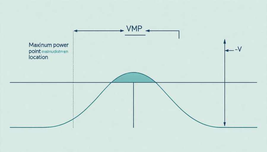
VMPP (Maximum Power Point Voltage) optimization stands at the forefront of modern solar photovoltaic system design, driving critical decisions in array configuration and inverter selection to maximize system efficiency. As solar cell technologies advance, understanding VMPP characteristics becomes increasingly vital for achieving optimal power harvest across varying environmental conditions. This parameter, representing the voltage at which a PV module delivers its peak power output, directly influences string sizing, inverter compatibility, and overall system performance. For design engineers and solar professionals, mastering VMPP calculations and their practical applications enables precise system modeling, reduced power losses, and enhanced energy yield throughout the installation’s lifetime. Recent developments in smart inverter technology and module-level power electronics have further elevated the importance of VMPP considerations in modern solar deployments, making it an essential concept for anyone involved in photovoltaic system design and optimization.
Understanding VMPP in Solar PV Systems
Key Factors Affecting VMPP
The maximum power point voltage (VMPP) is significantly influenced by various environmental factors affecting performance. Temperature plays a crucial role, with higher temperatures leading to a decrease in VMPP. For every degree Celsius increase above standard test conditions (25°C), VMPP typically decreases by 0.3% to 0.5%, impacting overall system efficiency.
Solar irradiance levels directly affect VMPP, with higher irradiance generally resulting in increased voltage output. However, this relationship isn’t strictly linear, as the voltage tends to stabilize at higher irradiance levels while current continues to increase. Partial shading conditions can significantly alter VMPP characteristics, potentially creating multiple local maximum power points.
Atmospheric conditions such as humidity, dust accumulation, and air mass index also influence VMPP. High humidity can lead to increased surface soiling and reduced voltage output, while dust accumulation creates additional resistance that affects voltage optimization. Understanding these factors is essential for system designers to implement effective MPPT algorithms and maximize energy harvest throughout varying environmental conditions.
VMPP vs. System Voltage
The relationship between VMPP and system voltage plays a crucial role in photovoltaic system design and performance optimization. When designing a solar array, engineers must consider how individual module VMPP values will contribute to the overall system voltage requirements. Multiple modules connected in series combine their VMPP values, while parallel connections maintain the same voltage level across module strings.
System designers must ensure that the cumulative VMPP of the array remains within the operating voltage window of the chosen inverter. This consideration becomes particularly important in extreme temperature conditions, as VMPP varies inversely with temperature. During cold weather, VMPP increases, potentially approaching the inverter’s maximum voltage limit, while hot conditions decrease VMPP, potentially affecting system efficiency.
To maintain optimal performance, system voltage calculations must account for both standard test conditions (STC) and real-world operating conditions. Engineers typically include a safety margin in their calculations to accommodate voltage fluctuations while ensuring the system operates within the inverter’s MPPT voltage range throughout the year. This approach helps maximize energy harvest while maintaining system reliability and compliance with electrical codes.
Optimizing PV Array Layout for VMPP
Series vs. Parallel Connections
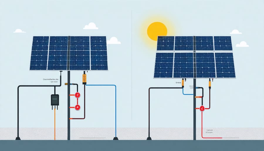
The configuration of solar panels significantly influences their VMPP characteristics, with series and parallel connections offering distinct advantages and operational considerations. In series connections, the voltage of individual panels adds up while current remains constant, resulting in a higher system VMPP. This arrangement is particularly beneficial for minimizing voltage drop in long cable runs and achieving optimal array configuration for most grid-tied inverters.
Parallel connections, conversely, maintain the same voltage while summing the current from each panel. This configuration keeps VMPP at the level of a single panel but increases the overall current capacity. Such arrangements are particularly useful when dealing with partial shading conditions, as the impact of shaded panels is less severe on the system’s overall performance.
The choice between series and parallel connections often depends on specific installation requirements, including inverter specifications, environmental conditions, and system size. Hybrid configurations, combining both series and parallel connections, can offer the best of both worlds by balancing voltage and current requirements while maintaining system efficiency. Understanding these relationships is crucial for system designers to maximize power output and ensure compatible operation with downstream components.
String Sizing Calculations
The calculation of optimal string sizes in photovoltaic systems requires careful consideration of VMPP values to ensure maximum system efficiency. The fundamental equation for determining string size is:
String Size = Maximum System Voltage / Module VMPP (at lowest expected temperature)
This calculation must account for temperature coefficients, as VMPP varies inversely with temperature. The formula for temperature-adjusted VMPP is:
VMPP(adj) = VMPP(STC) × [1 + (TC × ΔT)]
Where:
– VMPP(STC) is the voltage at maximum power point under standard test conditions
– TC is the temperature coefficient (typically -0.3% to -0.4% per °C)
– ΔT is the temperature difference from STC
For safety margin calculations, engineers typically use:
– Minimum design temperature: local record low -10°C
– Maximum design temperature: local record high +20°C
The maximum number of modules in series should not exceed:
Max Modules = (Inverter Max DC Voltage × Safety Factor) / VMPP(adj at minimum temp)
Similarly, the minimum number of modules must maintain:
Min Modules = (Inverter MPPT Lower Limit) / VMPP(adj at maximum temp)
These calculations ensure optimal power production while maintaining system safety and compatibility with inverter specifications. Regular validation of these calculations against manufacturer specifications is essential for system reliability.
Inverter Selection and VMPP Windows
The inverter selection process must carefully consider the VMPP characteristics of the PV array to ensure optimal system performance. The inverter’s voltage operating window should encompass the array’s VMPP range across all expected operating conditions. This compatibility is crucial for maximizing power harvest throughout the system’s lifetime.
Manufacturers specify minimum and maximum MPPT voltage ranges for their inverters, typically between 200V and 800V for string inverters. The array’s VMPP must remain within these limits during both cold winter mornings, when module voltage is highest, and hot summer afternoons, when voltage drops significantly. Temperature coefficients of the modules must be factored into these calculations.
When designing multi-string configurations, engineers must ensure that parallel strings have matched VMPP characteristics to prevent mismatch losses. The number of modules in series should be calculated to maintain VMPP within the inverter’s operating window while accounting for voltage variations due to temperature and irradiance changes.
Modern inverters often feature multiple MPPT channels, allowing for greater flexibility in string configurations and orientation. However, each MPPT channel must still be properly matched to its connected string’s VMPP characteristics to maintain optimal power point tracking efficiency.
Best Practices for VMPP-Based Layout Design
Temperature Compensation Strategies
Temperature variations significantly impact the maximum power point voltage (VMPP) of photovoltaic modules, necessitating careful consideration in system design and operation. As module temperature increases, VMPP typically decreases at a rate of approximately -0.3% to -0.4% per degree Celsius, affecting overall system performance.
To effectively compensate for these temperature-induced variations, several strategies are employed in modern solar installations. Temperature coefficients provided by manufacturers serve as crucial reference points for calculating VMPP adjustments across different operating conditions. These coefficients enable system designers to predict voltage behavior and implement appropriate compensation measures.
Advanced MPPT (Maximum Power Point Tracking) algorithms incorporate temperature sensors and real-time adjustment capabilities to optimize VMPP continuously. These systems utilize temperature feedback loops to modify tracking parameters, ensuring optimal power extraction despite thermal fluctuations.
Design engineers commonly employ safety factors in their calculations, accounting for both extreme cold conditions (which increase VMPP) and high-temperature scenarios (which decrease VMPP). This approach typically involves:
– Calculating maximum VMPP at lowest expected operating temperatures
– Determining minimum VMPP at highest expected operating temperatures
– Implementing appropriate voltage windows in inverter selection
– Installing temperature monitoring systems for real-time compensation
By implementing these temperature compensation strategies, system designers can ensure reliable operation and maximize energy yield across varying environmental conditions, maintaining optimal power output throughout the year.
Shading Considerations
Partial shading represents a significant challenge in photovoltaic systems, directly impacting the voltage at maximum power point (VMPP). When solar cells within a module experience uneven shading, multiple local maximum power points can emerge, complicating the system’s ability to identify and operate at the true global VMPP.
The effects of partial shading on VMPP can reduce system efficiency by 20-30% if not properly managed. Common causes include nearby structures, trees, clouds, and soiling. When shading occurs, bypass diodes activate to prevent hot spots and maintain some power output, but this creates characteristic steps in the I-V curve and shifts the VMPP.
To mitigate these effects, several strategies can be implemented. Module-level power electronics (MLPEs) such as power optimizers or microinverters can track individual module VMPPs, maximizing energy harvest despite partial shading. Advanced MPPT algorithms specifically designed for partial shading conditions can better navigate multiple power peaks.
System designers should conduct thorough shade analysis during planning phases and consider module arrangement patterns that minimize the impact of predictable shading patterns. Regular maintenance, including cleaning and vegetation management, helps prevent unnecessary shading losses. Additionally, selecting modules with half-cell technology or smart module solutions can improve system resilience to partial shading effects.
Tools and Software for VMPP Optimization
Several specialized software tools and design platforms are available to assist engineers and system designers in optimizing VMPP calculations and overall photovoltaic system performance. PVsyst stands out as an industry-standard software package, offering comprehensive modeling capabilities for VMPP characteristics across different environmental conditions and system configurations.
MATLAB/Simulink provides powerful simulation environments where professionals can develop custom VMPP tracking algorithms and analyze system behavior under various operating scenarios. Its flexibility allows for detailed mathematical modeling and real-time system optimization.
For field measurements and on-site analysis, portable I-V curve tracers like the Solmetric PV Analyzer and HT Instruments I-V400w enable technicians to verify actual VMPP values against theoretical calculations. These devices offer instant feedback on module performance and help identify potential optimization opportunities.
SAM (System Advisor Model), developed by the National Renewable Energy Laboratory (NREL), offers free access to sophisticated modeling tools. It includes detailed VMPP analysis capabilities and comprehensive financial assessment features, making it particularly valuable for both technical optimization and project feasibility studies.
AutoCAD Solar and HelioScope provide specialized design interfaces for solar PV systems, incorporating VMPP considerations into their layout optimization algorithms. These tools help designers achieve optimal string configurations while accounting for voltage constraints and maximum power point characteristics.
Modern monitoring platforms like SolarEdge and Enphase’s Enlighten integrate VMPP tracking data with real-time performance analytics, allowing system operators to ensure optimal operation throughout the system’s lifetime. These platforms often include mobile applications for remote monitoring and adjustment of VMPP parameters.
For educational purposes, PVLIB Python offers an open-source framework that enables researchers and students to develop and test VMPP optimization algorithms. This tool is particularly valuable in academic settings and research institutions where custom solutions are required.
Understanding and optimizing VMPP is crucial for maximizing the performance and efficiency of photovoltaic systems. Throughout this discussion, we’ve explored how the Maximum Power Point Voltage significantly influences solar array design, system configuration, and overall energy yield. The dynamic nature of VMPP, influenced by environmental factors such as temperature and irradiance, necessitates careful consideration during both the planning and operational phases of solar installations.
The implementation of effective MPPT algorithms, combined with proper inverter selection and string sizing, ensures that systems operate at their optimal voltage points consistently. This optimization not only enhances energy production but also contributes to the long-term reliability and economic viability of solar installations.
For system designers and engineers, maintaining awareness of VMPP characteristics is essential when making critical decisions about equipment selection and system architecture. The relationship between VMPP and factors such as partial shading, temperature coefficients, and array configuration directly impacts system performance and reliability.
As the solar industry continues to evolve, understanding VMPP becomes increasingly important for achieving higher system efficiencies and better returns on investment. Whether designing small residential installations or large utility-scale projects, proper VMPP consideration remains a fundamental aspect of successful photovoltaic system implementation. This knowledge ensures optimal system performance while contributing to the broader adoption of solar energy as a sustainable power source.