The electrical balance of system (BOS) represents the critical infrastructure that transforms solar panels from isolated components into a functioning, code-compliant power generation system. While photovoltaic modules capture sunlight, the electrical BOS—encompassing inverters, combiners, disconnects, grounding equipment, overcurrent protection, and monitoring systems—ensures that captured energy flows safely and efficiently to its destination. Poor installation practices in these components account for approximately 80% of solar system failures and safety incidents, making proper electrical BOS installation not merely a best practice but a professional imperative.
For aspiring installers entering the solar industry, mastering electrical BOS installation separates competent technicians from true professionals. This expertise directly impacts system performance, longevity, safety compliance, and ultimately, the financial returns that clients depend upon. The National Electrical Code dedicates Article 690 specifically to solar photovoltaic system installation, reflecting the complexity and critical nature of these systems.
This comprehensive guide addresses the complete electrical BOS installation workflow—from pre-installation planning and component selection through final commissioning and testing. You will gain practical knowledge of proper conductor sizing, grounding techniques, equipment placement strategies, weatherproofing methods, and systematic troubleshooting approaches. Each section bridges theory with field-tested practices, providing the technical foundation and hands-on guidance necessary to execute installations that meet or exceed industry standards.
Whether you are completing your first commercial installation or refining techniques developed over multiple residential projects, this resource delivers actionable insights that enhance installation quality, reduce callbacks, and build the professional reputation essential for long-term success in the photovoltaic industry.
Understanding Electrical Balance-of-System Components
Core Electrical BOS Components
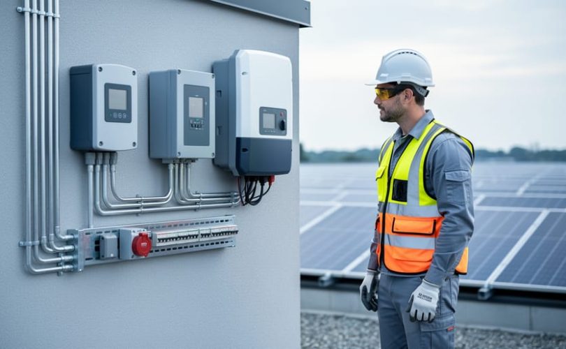
The electrical balance of system encompasses several critical components that work together to convert, manage, and safely deliver solar-generated electricity. Understanding each element’s function and proper implementation is essential for efficient system operation and regulatory compliance.
Inverters serve as the heart of any photovoltaic system, converting direct current from solar panels into alternating current suitable for grid connection or building consumption. String inverters, microinverters, and power optimizers each offer distinct advantages depending on system size, shading conditions, and monitoring requirements. Proper inverter sizing requires careful analysis of array voltage ranges, maximum power point tracking capabilities, and ambient temperature considerations to ensure optimal performance across varying conditions.
Combiner boxes consolidate multiple strings of solar panels into a single circuit, reducing wiring complexity and providing a centralized point for overcurrent protection. These enclosures typically house fuses or circuit breakers rated to handle the combined current of connected strings while offering a convenient location for array isolation during maintenance procedures. Modern combiner boxes increasingly incorporate monitoring capabilities and surge protection devices to enhance system reliability.
Disconnects provide critical safety functions by enabling complete electrical isolation of system components. AC and DC disconnect switches must be readily accessible, clearly labeled, and rated for appropriate voltage and current levels. These devices protect maintenance personnel and emergency responders while facilitating troubleshooting and component replacement.
Wiring and conduits form the electrical pathway connecting all system components. Proper conductor sizing accounts for current-carrying capacity, voltage drop limitations, and temperature derating factors. Conduit systems protect wiring from environmental exposure, mechanical damage, and ultraviolet degradation while meeting National Electrical Code requirements for installation methods and fill ratios.
Junction boxes serve as transition points where circuit configurations change or where connections between different wiring types occur. These enclosures must provide adequate space for wire terminations and maintain appropriate ingress protection ratings for their installation environment.
Grounding equipment establishes electrical safety by providing fault current pathways and lightning protection. Equipment grounding conductors, grounding electrode systems, and bonding jumpers work collectively to prevent dangerous voltage potentials and ensure proper protective device operation during fault conditions.
The Role of BOS in System Performance
The electrical balance of system directly influences multiple dimensions of photovoltaic system performance, making it a critical determinant of project success. Properly specified and installed BOS components typically account for 15-25% of total system efficiency, with suboptimal installations potentially reducing energy yield by 10% or more annually.
System efficiency begins at the conductor level, where undersized wiring creates resistive losses that convert usable electricity into waste heat. Quality inverters, properly matched to array characteristics, maximize power point tracking and minimize conversion losses. String configuration, optimized through careful BOS design, ensures modules operate within ideal voltage ranges throughout varying environmental conditions.
Safety compliance represents another essential performance dimension. BOS components provide the protective infrastructure required by the National Electrical Code and local authorities having jurisdiction. Rapid shutdown systems, arc fault protection, and proper grounding safeguard both installation personnel and system operators while ensuring insurability and permitting approval.
The relationship between BOS quality and return on investment becomes evident through lifecycle analysis. While premium components increase upfront costs by 8-12%, they deliver measurably higher energy production, reduced maintenance requirements, and extended system longevity. Research conducted through university partnerships demonstrates that systems with properly engineered BOS installations achieve 95-98% of theoretical energy output, compared to 80-90% for installations with compromised component selection or installation practices. This performance differential compounds over 25-year system lifespans, fundamentally affecting project economics and sustainability outcomes.
Pre-Installation Planning and Assessment
Site Assessment and Electrical Load Analysis
A comprehensive site assessment forms the foundation of any successful solar photovoltaic installation, directly influencing the design and performance of the electrical balance of system. This critical preliminary phase requires systematic evaluation of multiple technical and physical parameters to ensure proper system integration and compliance with applicable codes.
Begin by conducting a thorough electrical load analysis to determine the facility’s energy consumption patterns. Review at least twelve months of utility bills to identify baseline usage, peak demand periods, and seasonal variations. This historical data informs sizing decisions for both the PV array and associated BOS components. Document the existing electrical service characteristics, including voltage level (120/240V single-phase or 120/208V three-phase), service ampacity, and available fault current ratings. These specifications directly impact conductor sizing, overcurrent protection device selection, and equipment ratings throughout the system.
Evaluate the main service panel or switchboard for available capacity and physical space to accommodate new circuit breakers or disconnects. Apply the 120 percent rule specified in the National Electrical Code, which states that the sum of the main breaker and solar backfed breaker ratings cannot exceed 120 percent of the busbar rating. If inadequate capacity exists, consider alternative interconnection methods such as line-side taps or service upgrades.
Assess the proposed equipment locations for inverters, combiners, disconnects, and metering equipment. Consider proximity to the array, existing electrical infrastructure, and accessibility for maintenance. Environmental factors including ambient temperature ranges, exposure to moisture, and ventilation requirements influence equipment specifications and enclosure ratings. Identify the utility interconnection point and review applicable interconnection requirements, which vary by jurisdiction and utility provider. Understanding these parameters early prevents costly redesigns and ensures the BOS design meets all technical and regulatory requirements while optimizing system performance and installation efficiency.
Code Compliance and Permitting Requirements
Navigating code compliance and permitting represents a critical phase in any electrical balance-of-system installation. The National Electrical Code (NEC), specifically Articles 690 and 705, establishes fundamental requirements for photovoltaic system installations, covering conductor sizing, overcurrent protection, grounding, and disconnecting means. Installers must maintain current knowledge of NEC updates, as the code undergoes revisions every three years to address evolving technologies and safety practices.
Beyond federal standards, local building codes and amendments often impose additional requirements that vary significantly by jurisdiction. Many municipalities adopt the NEC with local modifications, creating unique compliance landscapes that installers must research thoroughly. Contacting the local Authority Having Jurisdiction (AHJ) early in the planning process helps identify specific requirements, submittal procedures, and inspection protocols that apply to your project.
Utility interconnection requirements constitute another essential compliance layer. Electric utilities maintain technical standards for grid-connected systems, including equipment specifications, anti-islanding protection, and metering configurations. Installers should submit interconnection applications concurrently with building permit applications to avoid project delays, as utility approval processes can extend several weeks.
The permitting process typically requires detailed documentation including single-line diagrams, equipment specifications, structural calculations, and site plans. Working with educational institutions and training programs helps aspiring professionals develop competency in permit preparation and code interpretation. Maintaining open communication with inspectors and promptly addressing plan review comments ensures efficient approval and demonstrates professional accountability throughout the installation process.
Component Selection and Compatibility
Selecting compatible components represents one of the most critical decisions in electrical balance of system design. The interoperability between photovoltaic modules, inverters, charge controllers, and monitoring equipment directly impacts system performance, safety, and longevity. Begin by carefully reviewing module specifications, particularly voltage ratings at maximum power point, open-circuit voltage, and short-circuit current under varying temperature conditions. These parameters must align with inverter input specifications to prevent overvoltage conditions or underutilization of equipment capacity.
Inverter selection requires matching the combined string voltage and current to the device’s maximum power point tracking range and input current ratings. Consider environmental factors such as ambient temperature ranges and altitude, which affect both module output and inverter derating requirements. String sizing calculations should account for worst-case temperature scenarios to ensure voltage remains within acceptable limits throughout seasonal variations.
When specifying wire gauges, disconnect switches, circuit breakers, and combiner boxes, verify that current ratings exceed the calculated maximum circuit current by appropriate safety factors as mandated by electrical codes. Component voltage ratings must similarly exceed system maximum voltage with adequate margin. Grounding equipment compatibility deserves particular attention, ensuring that grounding conductors, lugs, and bonding hardware meet specifications for both AC and DC sides of the installation. Universities conducting photovoltaic research emphasize that systematic compatibility verification during the design phase prevents costly field modifications and ensures reliable system operation throughout the installation’s service life.
Wiring and Electrical Connection Best Practices
Wire Sizing and Selection
Proper wire sizing represents a critical safety and performance consideration in photovoltaic system installation. Undersized conductors can lead to excessive voltage drop, reduced system efficiency, overheating, and potential fire hazards. The National Electrical Code provides comprehensive requirements for calculating appropriate wire gauge based on multiple factors.
Current-carrying capacity, or ampacity, serves as the primary sizing criterion. Calculate the maximum current by taking the module or string short-circuit current and multiplying by 1.25 as required by NEC Article 690. For example, a string producing 8 amps would require wire rated for at least 10 amps continuous duty. However, this represents only the starting point for proper conductor selection.
Voltage drop considerations significantly impact system performance, particularly over long wire runs between the array and inverter. Industry best practices recommend limiting voltage drop to 2 percent or less for optimal efficiency. Use Ohm’s Law and conductor resistance tables to calculate expected voltage drop based on distance, current, and wire gauge. Increasing conductor size by one or two gauges often proves cost-effective compared to energy losses over the system’s lifetime.
Temperature derating factors must be applied when ambient conditions exceed standard rating temperatures of 30 degrees Celsius. High-temperature environments, such as attics or unventilated conduits, require using correction factors from NEC Table 310.15(B)(2)(a) to prevent insulation degradation.
Conduit fill requirements limit the number and size of conductors within raceways, ensuring adequate heat dissipation and preventing installation damage during wire pulling operations.
Proper Termination Techniques
Establishing reliable electrical connections is fundamental to system performance and longevity in photovoltaic installations. Proper termination techniques prevent power losses, reduce fire hazards, and ensure compliance with electrical codes.
For wire-to-wire and wire-to-terminal connections, crimp connectors provide superior reliability when installed correctly. Select crimp connectors rated for the wire gauge and environmental conditions, ensuring they meet UL or equivalent certification standards. Use calibrated crimping tools designed for your specific connector type, as improper crimping tools can result in loose connections or conductor damage. A properly crimped connection should show no exposed conductor strands and require significant force to separate.
MC4 connectors have become the industry standard for module-level connections due to their weather resistance and ease of installation. When terminating MC4 connectors, strip wire insulation to the precise length specified by the manufacturer, typically 7-9 millimeters. Insert the conductor fully into the contact pin before crimping, then assemble the connector housing until you hear a distinct click. Always verify polarity before mating connectors, as reversing connections can damage system components.
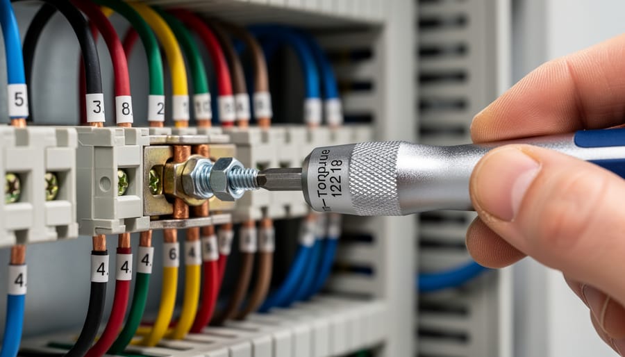
Torque specifications are critical for busbar, terminal block, and combiner box connections. Under-torqued connections create high-resistance joints that generate heat and accelerate degradation. Over-torquing can strip threads or crack terminals. Use calibrated torque wrenches or screwdrivers and follow manufacturer specifications, typically ranging from 7 to 9 inch-pounds for smaller terminals and up to 35 inch-pounds for larger connections.
Prevent common termination errors by maintaining clean work surfaces, protecting connections from moisture during installation, and conducting visual inspections before energizing systems.
Cable Management and Protection
Proper cable management protects electrical wiring from environmental hazards while ensuring system reliability and facilitating future maintenance. The selection and installation of conduit systems, cable trays, and securing methods directly impact long-term system performance and compliance with electrical codes.
Conduit systems provide the primary physical protection for photovoltaic wiring. Metallic conduits, including electrical metallic tubing (EMT) and rigid metal conduit (RMC), offer superior mechanical protection and grounding continuity. Non-metallic options like PVC conduit resist corrosion in coastal or chemically aggressive environments. When routing conduit, maintain minimum bend radius specifications—typically six times the conduit diameter for smooth bends—to prevent cable damage during installation and ensure proper wire fill ratios per National Electrical Code Article 310.
Cable trays offer accessible routing solutions for larger installations where frequent system modifications are anticipated. Ladder-style and channel trays accommodate multiple circuits while maintaining separation between different voltage levels. Secure cables within trays using approved fasteners at intervals not exceeding manufacturer specifications, typically every 24 to 36 inches for horizontal runs and 12 inches for vertical routing.
Environmental protection requires careful attention to sealing and drainage. Install conduit with slight downward slopes toward drainage points to prevent water accumulation. Use appropriate sealants and weatherproof fittings at all junction points. For rooftop installations, employ UV-resistant cable ties and protective sleeving rated for continuous sunlight exposure.
Maintain accessibility by installing cables with adequate slack for future servicing and clearly labeling all circuits according to system documentation requirements.
Grounding and Bonding Standards
Equipment Grounding Requirements
Proper equipment grounding forms a critical component of photovoltaic system safety, protecting both personnel and equipment from electrical hazards. All conductive equipment in a PV array must be grounded according to National Electrical Code Article 250 and manufacturer specifications to establish a reliable path for fault currents.
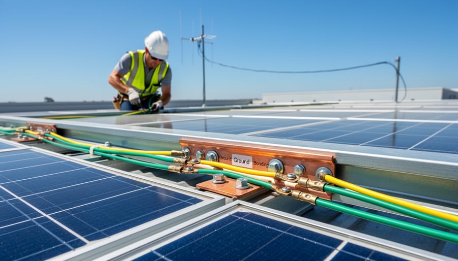
Module frames and mounting structures require grounding through listed equipment grounding conductors or approved bonding devices. Each array frame section must connect to the grounding system using properly sized copper conductors, typically 6 AWG minimum for most residential installations. Bonding jumpers between rail sections ensure electrical continuity throughout the racking system, preventing potential differences that could create shock hazards.
Inverters demand special attention to grounding requirements. Both the equipment grounding conductor and grounding electrode conductor must terminate at designated points within the inverter enclosure. The grounding electrode system typically consists of ground rods, building steel connections, or concrete-encased electrodes meeting code specifications.
Junction boxes, combiner boxes, and disconnects require individual grounding connections. All metal enclosures must bond to the equipment grounding conductor using listed pressure connectors or exothermic welding techniques. Torque specifications for grounding connections must follow manufacturer guidelines to ensure reliable electrical contact.
Regular testing of grounding system integrity forms part of comprehensive safety protocols. Ground resistance testing should verify values below 25 ohms, with lower values preferred for optimal lightning protection and fault clearing performance.
System Grounding and Bonding Configurations
Proper system grounding and bonding form the foundation of electrical safety in photovoltaic installations, protecting both personnel and equipment from electrical hazards. Understanding the fundamental differences between grounded and ungrounded systems is essential for aspiring professionals entering the solar industry.
Grounded systems intentionally connect one current-carrying conductor to earth, typically the neutral in residential applications. This configuration provides a reference point for system voltage and facilitates overcurrent device operation during ground faults. Ungrounded systems, conversely, maintain electrical isolation from earth, though equipment grounding conductors remain mandatory for safety. The National Electrical Code specifies requirements for both configurations, with most residential and commercial PV systems employing grounded designs.
The grounding electrode system establishes the critical connection between electrical equipment and earth. Effective installations incorporate multiple electrodes including ground rods, concrete-encased electrodes (Ufer grounds), and connections to metal water pipes where applicable. Electrodes must meet minimum depth and spacing requirements, typically eight feet for ground rods with ten-foot separation between multiple rods. Resistance testing verifies system effectiveness, with readings below 25 ohms considered acceptable for most applications.
Bonding creates continuous low-impedance paths for fault currents throughout the installation. Equipment grounding conductors must connect all metallic components including module frames, racking systems, junction boxes, and inverter enclosures. Bonding jumpers bridge discontinuities in the grounding path, while listed bonding devices ensure reliable mechanical and electrical connections. Regular inspection confirms bonding integrity, particularly at connection points susceptible to corrosion or mechanical stress, maintaining system safety throughout operational life.
Inverter and Disconnect Installation
Inverter Placement and Mounting
Strategic inverter placement significantly impacts system performance, longevity, and maintenance efficiency. Following proper inverter selection and compatibility assessment, installers must evaluate multiple environmental and practical factors when determining optimal mounting locations.
Temperature management represents the primary consideration for inverter placement. Inverters generate substantial heat during operation, and excessive ambient temperatures reduce efficiency and accelerate component degradation. Install inverters in shaded, well-ventilated areas away from direct sunlight. Indoor installations in conditioned spaces typically provide superior thermal performance compared to outdoor mounting. When outdoor installation is necessary, utilize manufacturer-approved enclosures with adequate ventilation and ensure clearances specified in installation manuals are maintained on all sides.
Accessibility for routine maintenance and troubleshooting directly affects long-term system reliability. Position inverters at eye level when possible, allowing technicians to easily view displays and operate controls without ladders or special equipment. Maintain minimum clearance requirements around the inverter—typically 24 inches on access sides—to facilitate safe servicing and component replacement.
Proximity to the main service panel minimizes voltage drop and reduces conduit runs, decreasing installation costs while improving system efficiency. However, balance this consideration against environmental protection requirements. Avoid locations prone to moisture accumulation, flooding, or physical damage. Ensure mounting surfaces provide adequate structural support for inverter weight and comply with manufacturer specifications and local building codes.
Required Disconnects and Safety Switches
Proper disconnect switches represent essential safety mechanisms in photovoltaic installations, providing both emergency shutdown capability and safe isolation for maintenance activities. The National Electrical Code mandates specific disconnect requirements at various system points to protect personnel and equipment.
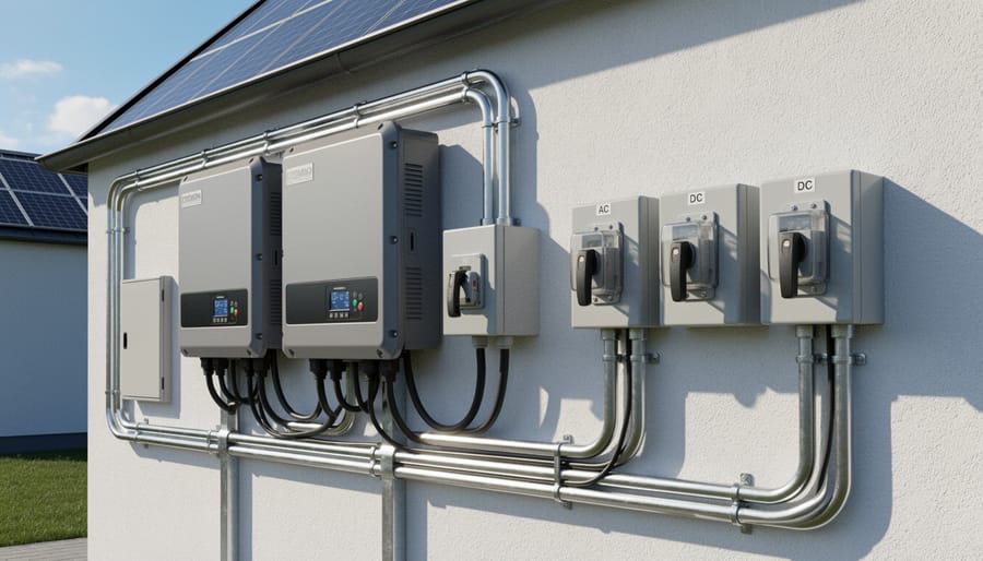
AC disconnects must be installed between the inverter output and the utility connection point, typically positioned near the main service panel or meter. These switches enable utility workers and first responders to de-energize the solar system quickly during emergencies. The disconnect should be readily accessible, weatherproof when located outdoors, and rated for the system’s maximum current and voltage specifications.
DC disconnects serve equally critical functions on the array side of the system. Installing disconnects between the photovoltaic array and the inverter allows technicians to isolate the DC portion safely during maintenance or troubleshooting. Many modern string inverters integrate DC disconnects internally, streamlining installation while maintaining code compliance.
Rapid shutdown systems have become mandatory under NEC 2017 and subsequent editions for most residential and commercial installations. These systems ensure that conductors beyond one foot from the array remain de-energized within thirty seconds of activation, significantly reducing electric shock hazards for firefighters and emergency personnel. Module-level power electronics or specialized rapid shutdown devices embedded at the array level satisfy these requirements.
Proper labeling constitutes a non-negotiable safety requirement. All disconnect switches must display durable, weather-resistant labels identifying their function, voltage levels, and the location of corresponding disconnects. Emergency responders rely on clear labeling to assess system hazards quickly, making this simple step potentially life-saving during crisis situations.
Testing, Commissioning, and Documentation
Pre-Energization Testing Procedures
Before energizing any photovoltaic system, comprehensive pre-energization testing validates electrical integrity and confirms compliance with safety standards. These procedures identify potential hazards that could compromise system performance or personnel safety during startup.
Begin with continuity testing across all series connections within each string. Using a digital multimeter, verify electrical continuity between module terminals, combiner box connections, and inverter inputs. This process detects loose connections, damaged conductors, or broken circuits that may have occurred during installation.
Insulation resistance testing follows continuity verification. Apply a megohmmeter (megger) between conductors and ground, testing at voltages specified by the National Electrical Code—typically 500-1000V for PV systems. Acceptable resistance values should exceed 1 megohm per system voltage rating. This test reveals insulation degradation, moisture intrusion, or damaged cable jackets that could create ground faults.
Polarity verification ensures proper positive and negative conductor identification throughout the array. Incorrect polarity creates dangerous reverse current conditions and potential equipment damage. Test each string individually before combining circuits, using a voltmeter to confirm voltage polarity matches connection documentation.
Ground fault testing validates the integrity of equipment grounding conductors and bonding connections. Measure resistance between ground points and verify values remain below 5 ohms. This quality control testing prevents electrical shock hazards and ensures proper ground fault protection device operation. Document all test results with date, location, and measured values for compliance records and future troubleshooting reference.
Documentation and Labeling Requirements
Proper documentation and labeling represent critical final steps in electrical balance of system installation, ensuring code compliance, facilitating inspections, and enabling safe future maintenance. Comprehensive as-built drawings must accurately reflect the installed system configuration, including all modifications made during construction that deviate from original plans. These drawings should document conductor routing, equipment locations, conduit pathways, grounding electrode placements, and circuit identifications with precise measurements and specifications.
System labeling requirements under the National Electrical Code mandate clear identification of all components, circuits, and safety features. Critical labels include photovoltaic source and output circuit identifications, maximum system voltage warnings, rapid shutdown boundary markings, arc-fault protection indicators, and equipment disconnects. Labels must be durable, weather-resistant, and legible under expected environmental conditions, using materials that withstand UV exposure and temperature extremes.
Installation records should include equipment serial numbers, commissioning test results, torque specifications applied to terminations, and manufacturer warranty documentation. Many jurisdictions require these records for permit closure and subsequent inspections. Creating a comprehensive operations and maintenance manual that includes single-line diagrams, equipment specifications, emergency procedures, and contact information proves invaluable for system owners and future service technicians.
Academic institutions and training programs emphasize documentation skills as foundational competencies for photovoltaic professionals. Maintaining meticulous records protects installers from liability, expedites troubleshooting efforts, and demonstrates professional workmanship. Digital documentation systems increasingly supplement traditional paper records, enabling efficient information sharing among project stakeholders while ensuring long-term accessibility for system lifecycle management.
Common Installation Mistakes and How to Avoid Them
Electrical Connection Failures
Electrical connection failures represent one of the most preventable yet potentially catastrophic issues in photovoltaic installations. These failures typically stem from four primary causes that installers must vigilantly address during every installation.
Improper torque application remains a leading cause of connection failures. Over-tightening conductors can damage wire strands, reduce the effective cross-sectional area, and create stress points that deteriorate over time. Conversely, under-tightening allows conductors to work loose due to thermal cycling, creating high-resistance connections that generate excessive heat. Always use calibrated torque wrenches and follow manufacturer-specified torque values, typically ranging from 7 to 15 Newton-meters for residential systems depending on terminal specifications.
Incorrect wire sizing creates immediate code violations and long-term safety hazards. Undersized conductors cannot safely carry design current loads, resulting in voltage drops exceeding three percent and dangerous overheating. Calculate ampacity requirements using NEC Article 690, accounting for temperature correction factors and conduit fill derating. For example, a 30-amp circuit in a 75-degree Celsius environment requires 10 AWG copper conductors, not the 12 AWG that might suffice under standard conditions.
Poor connection quality manifests through inadequate wire stripping, oxidized contact surfaces, mixed metal connections without proper anti-oxidant compounds, and loose terminal screws. These issues create resistance hotspots, increasing fire risk substantially. Studies conducted in collaboration with universities have documented connection temperatures exceeding 90 degrees Celsius in improperly executed installations, well above safe operating thresholds.
Code Violations and Safety Oversights
Electrical balance-of-system installations frequently encounter code compliance issues that delay inspections and compromise safety. Understanding these common violations enables professionals to avoid costly rework and ensures installations meet National Electrical Code requirements from the outset.
Grounding and bonding deficiencies represent the most prevalent code violations in solar installations. Inadequate equipment grounding conductor sizing, missing bonding jumpers between array frames, and improper grounding electrode connections create shock hazards and equipment damage risks. The NEC Article 690 specifies precise grounding requirements, including conductor sizing based on inverter output ratings and proper connection methods using listed connectors. Many installations fail inspection due to missing grounding labels or inadequate documentation of grounding resistance measurements.
Disconnect placement violations also cause significant inspection delays. Rapid shutdown disconnects must remain readily accessible and clearly visible, positioned within sight of the service equipment. Installations often fail when disconnects are placed inside locked enclosures without proper signage or located more than 10 feet from equipment they control. Additionally, outdoor disconnects require NEMA-rated weatherproof enclosures appropriate for local environmental conditions.
Labeling deficiencies constitute another frequent oversight. The NEC mandates specific labels indicating maximum system voltage, short-circuit current, and arc-flash hazard warnings at multiple locations throughout the system. Directory labels at service panels must identify all power sources, while conduit labels should indicate conductor purpose and voltage levels. Proper labeling not only ensures code compliance but also protects maintenance personnel and emergency responders during system troubleshooting or emergency situations.
Proper electrical balance of system installation represents far more than a technical checkbox in solar PV deployment—it fundamentally determines whether a system will deliver decades of reliable, safe performance or face premature failures and safety hazards. As this comprehensive examination has demonstrated, mastering BOS installation practices requires thorough understanding of electrical codes, meticulous attention to detail, rigorous testing protocols, and unwavering commitment to safety standards. The complexity of modern PV systems, with their sophisticated inverters, monitoring capabilities, and grid integration requirements, demands that installers continuously update their knowledge and refine their skills to keep pace with evolving technologies and regulatory frameworks.
For aspiring photovoltaic professionals, the pathway to excellence in electrical BOS installation begins with structured education and hands-on training. Mose Solar recognizes this critical need and has developed targeted professional certification programs designed to equip the next generation of installers with both theoretical knowledge and practical expertise. These educational initiatives, developed through collaboration with universities and industry experts, provide comprehensive coverage of installation best practices, code compliance, troubleshooting techniques, and emerging technologies. By investing in ongoing professional development, installers not only enhance their career prospects but also contribute to the broader mission of advancing solar energy adoption through quality workmanship that builds client confidence and system performance.