Arc flash incidents in photovoltaic systems release temperatures exceeding 35,000°F—hotter than the sun’s surface—transforming electrical energy into explosive thermal events that cause severe burns, hearing loss, and fatalities within milliseconds. Understanding arc flash protection isn’t optional for PV professionals; it’s the critical barrier between routine maintenance and catastrophic injury.
Identify your system’s incident energy levels through detailed arc flash studies before any energized work begins. Calculate the available fault current, clearing time of protective devices, and working distance to determine the arc flash boundary—the minimum safe approach distance for unprotected personnel. This quantitative assessment directly informs every subsequent safety decision, from personal protective equipment selection to procedural controls.
Select flame-resistant clothing and face shields rated for your system’s specific arc-rated cal/cm² exposure level, not generic safety gear. Equipment must meet NFPA 70E standards with properly rated arc thermal performance values matching your calculated incident energy levels. Inadequate PPE provides false confidence while offering zero protection against the actual hazard.
Implement lockout/tagout procedures and de-energization protocols as primary controls, reserving energized work exclusively for diagnostically necessary tasks where de-energization creates greater hazards. Engineering controls—current-limiting fuses, arc-resistant equipment, remote operation capabilities—reduce both incident probability and severity before relying solely on personal protective equipment.
The following sections provide comprehensive frameworks for assessing risks, selecting appropriate protection systems, and establishing robust operational procedures that transform regulatory compliance into practical workplace safety.
Understanding Arc Flash Hazards in PV Systems
What Makes PV Systems Particularly Vulnerable
Photovoltaic systems present unique arc flash challenges that distinguish them from conventional AC electrical installations. Understanding these vulnerabilities is essential for implementing effective protective measures and recognizing PV system hazards.
The most significant factor is the direct current (DC) nature of PV power. Unlike alternating current, which naturally crosses zero voltage 120 times per second, DC maintains constant voltage and current flow. This characteristic makes DC arcs substantially more difficult to extinguish once initiated. While AC arcs may self-extinguish at zero-crossing points, DC arcs sustain themselves indefinitely, creating prolonged exposure to extreme temperatures exceeding 35,000 degrees Fahrenheit.
PV arrays function as constant energy sources that cannot be easily disconnected from their power generation. Even with proper shutdown procedures, individual solar panels continue producing voltage and current whenever exposed to sunlight. This persistent energy availability means potential arc flash hazards remain present during maintenance, troubleshooting, and emergency response situations.
Series string configurations compound these risks by creating high voltage DC circuits, often reaching 600 to 1,500 volts in residential and commercial installations. These elevated voltages increase arc flash severity and extend the potential arc gap distance. Additionally, the distributed nature of PV systems means multiple potential fault points exist throughout rooftop arrays, combiner boxes, and inverter connections, multiplying exposure opportunities for personnel working on these installations.
The Physics Behind Arc Flash Events
An arc flash event occurs when electrical current travels through air between conductors or from a conductor to ground, creating an electrical explosion of extreme intensity. In photovoltaic systems, these incidents typically result from equipment failure, contamination, accidental contact with energized components, or improper work procedures. Understanding the physics underlying these events is essential for implementing effective protective measures.
When an arc forms, resistance in the air breaks down, allowing massive current flow that can reach tens of thousands of amperes. This instantaneous energy release generates temperatures exceeding 35,000 degrees Fahrenheit—four times hotter than the sun’s surface. The extreme heat vaporizes surrounding materials, including copper conductors and aluminum bus bars, creating a plasma state that expands rapidly outward.
The hazards from an arc flash event manifest in three primary forms. Thermal hazards pose the most significant threat, causing severe burns to exposed skin within milliseconds. The intense heat can ignite clothing and melt personal protective equipment that lacks adequate arc rating. Studies conducted in collaboration with universities have quantified the relationship between incident energy and burn severity, establishing safety thresholds measured in calories per square centimeter.
Pressure wave hazards result from rapid air expansion, generating blast forces that can rupture eardrums, cause internal injuries, and propel workers backward. The pressure wave also launches molten metal droplets at high velocity, creating projectile hazards that extend several feet from the arc source.
Light hazards include intense ultraviolet and infrared radiation capable of causing permanent retinal damage and temporary blindness. The brilliant flash can disorient workers, leading to falls or secondary injuries.
In photovoltaic installations, DC arc characteristics differ from AC systems, often sustaining longer duration due to the absence of current zero-crossing points, potentially increasing overall energy exposure.
Regulatory Standards and Safety Requirements
Key Standards Every PV Professional Must Know
Several critical standards govern arc flash protection in photovoltaic systems, each addressing specific safety aspects that professionals must understand and implement. The National Fire Protection Association’s NFPA 70E, Standard for Electrical Safety in the Workplace, serves as the foundational document for arc flash safety protocols. This standard establishes requirements for risk assessment procedures, selection of personal protective equipment, and implementation of safe work practices. It mandates arc flash hazard analysis for systems capable of delivering hazardous energy levels and prescribes approach boundaries that workers must observe.
The National Electrical Code (NEC), specifically Article 690 covering solar photovoltaic systems, addresses installation requirements that directly impact arc flash safety. This includes proper system grounding, overcurrent protection device selection, and disconnecting means placement. Compliance with NEC provisions reduces arc flash incident likelihood through proper system design.
IEEE Standard 1584, Guide for Performing Arc-Flash Hazard Calculations, provides calculation methodologies for determining incident energy levels and arc flash boundaries in PV systems. This standard enables accurate hazard assessment and appropriate safety measure implementation.
Additionally, OSHA safety requirements under 29 CFR 1910 Subpart S mandate employer responsibilities for electrical safety program development and implementation. These regulations require comprehensive worker training, hazard identification procedures, and documented safety protocols.
Understanding these interconnected standards enables PV professionals to develop comprehensive arc flash protection programs that satisfy regulatory requirements while ensuring personnel safety throughout system installation, operation, and maintenance activities.
Compliance and Documentation Requirements
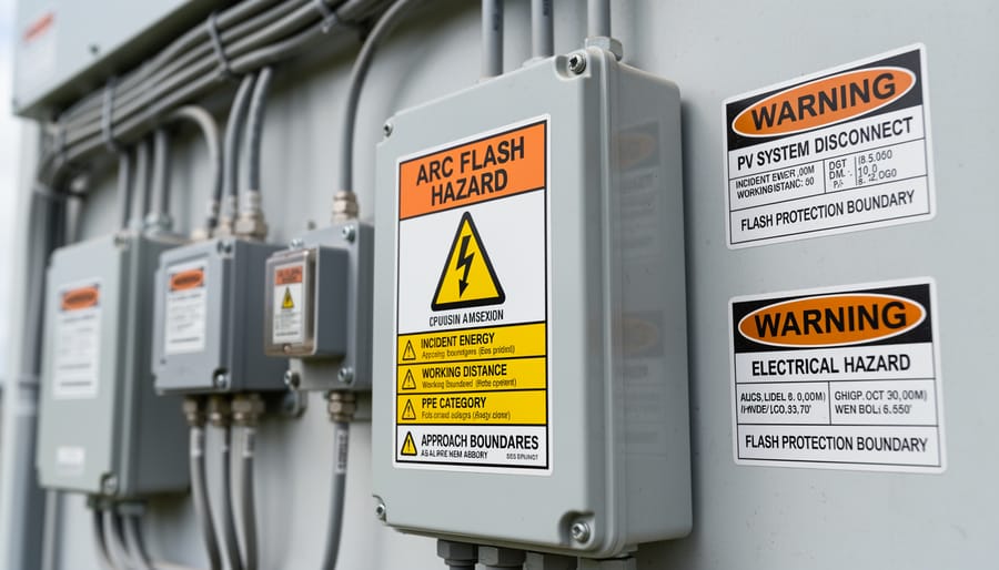
Proper compliance and documentation form the foundation of effective arc flash safety programs in photovoltaic installations. The National Electrical Code (NEC) Article 690.56 mandates that all PV systems with dc voltages exceeding 80 volts between conductors must display arc flash warning labels at equipment locations. These labels must clearly indicate the nominal system voltage, maximum available short-circuit current, and arc flash boundary distance.
Arc flash boundary calculations determine the safe approach distance where incident energy levels drop below 1.2 cal/cm². Professional assessments typically utilize IEEE 1584 methodology adapted for dc systems, though PV-specific standards like IEC 63027 provide more accurate modeling for solar installations. These calculations must account for string configuration, maximum power point tracking voltage ranges, and potential parallel fault contributions from multiple array segments.
Essential documentation includes single-line diagrams identifying all potential arc flash hazard locations, equipment specifications with interrupt ratings, and maintenance records demonstrating regular inspection schedules. Many jurisdictions require arc flash hazard analysis updates following system modifications or expansions. Working with accredited educational institutions and certification programs ensures personnel maintain current knowledge of evolving compliance standards while reinforcing organizational safety culture through systematic documentation practices and regular training verification records.
Essential Arc Flash Protection Equipment and PPE
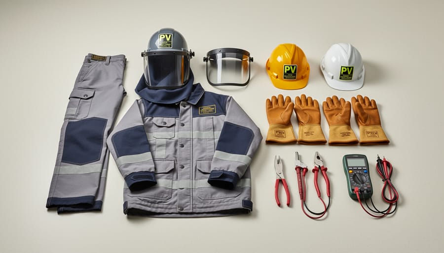
Selecting the Right Arc-Rated Clothing
Selecting appropriate arc-rated clothing requires understanding the Arc Thermal Performance Value (ATPV) system and matching protection levels to calculated incident energy. ATPV, measured in calories per square centimeter (cal/cm²), indicates the maximum incident energy a garment can withstand before causing a second-degree burn. Arc-rated clothing is categorized into hazard risk categories (HRC 1-4), with each level providing progressively higher protection.
For photovoltaic applications, begin by determining the incident energy level through arc flash calculations or label information at the work location. Once you know the incident energy value, select PPE with an ATPV rating equal to or greater than the calculated exposure. For example, if incident energy calculations indicate 8 cal/cm² exposure, minimum ATPV 8 clothing is required, though choosing the next higher category provides an additional safety margin.
Arc-rated clothing systems typically include flame-resistant shirts, pants, coveralls, jackets, and undergarments. In PV installations, common protection levels range from HRC 1 (4 cal/cm²) for basic maintenance work to HRC 2 or 3 (8-25 cal/cm²) for energized troubleshooting or connections. Multi-layer systems provide enhanced protection—an arc-rated shirt worn over an arc-rated undershirt increases the total ATPV rating.
Always verify that garments carry proper certification labels indicating ATPV ratings and compliance with ASTM F1506 standards. Replace damaged or contaminated arc-rated clothing immediately, as compromised fabric significantly reduces protective capabilities. Remember that conventional cotton or synthetic workwear provides no arc flash protection and should never substitute for certified arc-rated garments in electrical work environments.
Face and Eye Protection for PV Work
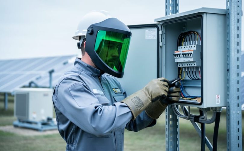
Protecting the face and eyes during photovoltaic system work requires specialized equipment rated for arc flash hazards. Arc-rated face shields serve as the primary barrier against intense light, heat, and projectiles generated during electrical faults. These shields must meet ASTM F2178 standards and display an Arc Thermal Performance Value (ATPV) matching or exceeding the calculated incident energy level at your work location. Unlike standard face protection, arc-rated shields use materials specifically engineered to resist ignition and maintain structural integrity during thermal events.
Safety glasses with side shields provide essential impact protection and should always be worn underneath face shields as secondary defense. For PV installations, select polycarbonate lenses offering both UV protection and high-velocity impact resistance. The dual-layer approach ensures comprehensive coverage, as face shields protect against broad thermal exposure while safety glasses safeguard against smaller debris.
Hard hats designed for electrical work must be Class E rated, providing dielectric protection up to 20,000 volts. When combined with arc-rated face shields, these systems create integrated head protection suitable for elevated photovoltaic maintenance tasks. Modern designs feature accessory slots allowing secure shield attachment without compromising the hard hat’s protective properties. Regular inspection of all face and eye protection components ensures continued reliability, particularly checking for cracks, warping, or degraded materials that could compromise performance during critical incidents.
Additional Protective Equipment and Tools
Beyond personal protective equipment, arc flash protection requires specialized tools and safety devices designed specifically for electrical work environments. Insulated tools form the first line of defense, featuring non-conductive handles and shafts rated for the voltage levels present in photovoltaic installations. These tools must meet ASTM F1505 standards, typically rated for 1000V AC or 1500V DC operations common in commercial and utility-scale solar arrays.
Non-contact voltage detectors provide critical verification that circuits are de-energized before work begins. For photovoltaic systems, detectors must accommodate both AC and DC voltage detection, with appropriate sensitivity ranges for solar installations. Live-line indicators offer visual confirmation of energized conductors, adding an additional verification layer during isolation procedures.
Temporary protective grounding equipment establishes equipotential zones and provides fault current paths during maintenance activities. Grounding sets must be sized appropriately for the available fault current and installed according to established sequences. Additional safety devices include arc-resistant barriers for enclosure modifications, cable covers for temporary installations, and lockout-tagout equipment essential for energy control procedures. These tools collectively create a comprehensive safety system that reduces both the probability and severity of arc flash incidents in photovoltaic operations.
Risk Assessment and Hazard Analysis for PV Installations
Calculating Incident Energy in PV Arrays
Determining incident energy levels in photovoltaic systems requires understanding unique DC power characteristics that differ significantly from traditional AC electrical systems. The incident energy, measured in calories per square centimeter (cal/cm²), quantifies the thermal energy exposure during an arc flash event and directly influences the appropriate personal protective equipment selection.
For PV arrays, incident energy calculations must account for multiple parallel source circuits, maximum power point tracking behavior, and the sustained nature of DC arcs. IEEE 1584 standard equations, traditionally developed for AC systems, require modifications when applied to solar installations. Industry professionals increasingly rely on specialized software tools that incorporate PV-specific variables including module specifications, array configuration, inverter characteristics, and environmental conditions.
The arc flash boundary represents the distance from the arc source where incident energy equals 1.2 cal/cm², the threshold requiring minimum flame-resistant clothing. In PV systems, this boundary extends further than comparable AC systems due to higher available fault currents and longer arc durations. Calculating this boundary involves determining the working distance, typically 18 inches for most PV maintenance tasks, and the maximum anticipated fault current.
Hazard risk categories, ranging from 0 to 4, correspond to specific incident energy levels and dictate required PPE levels. Category 0 applies when incident energy remains below 1.2 cal/cm², while Category 4 addresses exposures exceeding 40 cal/cm². Most residential PV systems fall within Categories 1-2, whereas large-scale commercial installations frequently require Category 3-4 protection during certain maintenance procedures.
Integration with rapid shutdown systems significantly reduces incident energy levels by de-energizing array conductors within seconds. Proper calculation methodologies should account for these protective measures, potentially lowering hazard categories and reducing PPE requirements while maintaining comprehensive worker protection throughout all operational scenarios.
Site-Specific Hazard Evaluation
Conducting a thorough site-specific hazard evaluation is essential before beginning any photovoltaic installation or maintenance work. This assessment must account for the unique characteristics of each system that influence arc flash severity and probability.
Begin by documenting system voltage levels, as higher voltages generate more dangerous arc flash events. DC systems present particular challenges since direct current arcs are harder to extinguish than alternating current arcs. Array configuration significantly impacts available fault current—larger arrays with multiple parallel strings can deliver substantially higher short-circuit currents, increasing incident energy levels.
Environmental factors require careful consideration. Ambient temperature affects conductor resistance and fault current calculations, while humidity and moisture can compromise insulation integrity and create unexpected conductive paths. Installations in coastal areas face accelerated corrosion that may degrade electrical connections over time, increasing arc flash risk.
Equipment age and maintenance history provide valuable context. Older inverters and combiner boxes may lack modern arc fault detection features, while poorly maintained connections present higher failure probabilities. Document all findings, including equipment ratings, conductor specifications, and protective device settings. This comprehensive evaluation forms the foundation for accurate incident energy calculations and appropriate personal protective equipment selection, ensuring worker safety aligns with actual site conditions rather than generic assumptions.
Engineering Controls and System Design Strategies
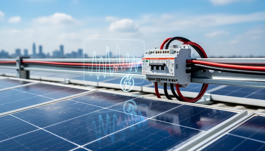
DC Arc Fault Circuit Interrupters and Protection Devices
Arc Fault Circuit Interrupters (AFCIs) represent a critical advancement in DC arc fault protection for photovoltaic systems, addressing one of the most significant fire and safety hazards in solar installations. These specialized devices continuously monitor electrical circuits for the characteristic signatures of dangerous arcing conditions, distinguishing between normal switching arcs and potentially hazardous series or parallel arcs that can generate temperatures exceeding 6,000 degrees Fahrenheit.
Modern AFCI technology employs sophisticated algorithms that analyze current waveforms, detecting the high-frequency noise patterns associated with arc faults. When an arc fault is identified, the device interrupts the circuit within milliseconds, preventing the escalation of a minor fault into a catastrophic fire or explosion. This rapid response is particularly crucial in PV systems where high DC voltages can sustain arcs more readily than AC circuits.
The 2017 National Electrical Code mandated AFCI protection for PV systems, recognizing their effectiveness in reducing arc flash incidents. These devices integrate seamlessly with rapid shutdown systems, which are now required to limit conductor voltage within 30 seconds of activation. Rapid shutdown technology works in concert with AFCIs by de-energizing arrays during emergencies or maintenance, significantly reducing arc flash exposure for first responders and technicians performing installation safety precautions.
Additional protective devices include DC-rated fuses, circuit breakers, and ground fault protection equipment, which collectively form a comprehensive defense system. Universities collaborating on PV safety research continue advancing AFCI sensitivity and reliability, ensuring these devices minimize nuisance tripping while maintaining rigorous protection standards.
System Design Best Practices for Arc Flash Mitigation
Effective arc flash mitigation begins at the design phase, where thoughtful engineering decisions can substantially reduce hazards before equipment installation. Proper string sizing serves as a fundamental protective measure—limiting the number of modules per string and maintaining voltage within conservative parameters reduces available fault current. Design engineers should calculate maximum short-circuit current values under worst-case scenarios and size conductors and overcurrent protection devices accordingly.
Grounding system design plays a critical role in arc flash prevention. A robust equipment grounding conductor network provides low-impedance paths for fault currents, enabling rapid protective device operation. All metallic enclosures, racking systems, and equipment frames must connect to a common grounding electrode system. Consider implementing supplementary grounding electrodes at inverter locations and combiner boxes to enhance fault current dissipation.
Equipment spacing requirements directly influence arc flash severity. Maintain adequate separation between energized components—generally 36 inches minimum for work clearances around equipment rated above 150 volts to ground. This spacing reduces thermal exposure during arc events and facilitates safer maintenance operations. Position combiner boxes, disconnect switches, and inverters to allow clear access paths and minimize worker exposure to energized components.
Design choices such as utilizing DC optimizers or microinverters inherently reduce arc flash risks by lowering system voltages and distributing power conversion. String inverters with rapid shutdown capabilities limit available energy during maintenance activities. Specifying arc fault circuit interrupters (AFCIs) in combiner boxes provides additional detection and interruption protection. These design elements complement emergency response protocols by reducing incident probability and severity. Coordinated protective device selection ensures cascading protection throughout the system, isolating faults at the lowest possible level while maintaining selective coordination.
Safe Work Practices and Operational Procedures
Pre-Work Safety Protocols
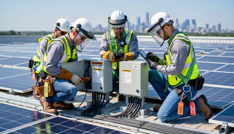
Establishing comprehensive pre-work safety protocols forms the foundation of effective arc flash protection in photovoltaic installations. These systematic procedures ensure that technicians approach energized equipment with appropriate safeguards and verification measures in place.
Begin with a thorough system assessment by reviewing single-line diagrams, equipment specifications, and previous arc flash study results. Document the system’s voltage levels, available fault current, and protective device characteristics. This information determines the arc flash boundary and required personal protective equipment levels. Coordinate with facility management to understand any recent system modifications that might affect hazard calculations.
The lockout/tagout procedure represents a critical component of pre-work safety. Before approaching any electrical equipment, identify all energy sources including DC circuits from PV arrays, AC circuits from inverters, and battery storage systems. Apply locks and tags according to NFPA 70E standards, ensuring each qualified worker uses their personal lockout device. Remember that PV systems present unique challenges because arrays continue generating power during daylight hours even when disconnected from loads.
Verification of de-energization requires testing with properly rated meters. After applying lockout devices, wait for capacitors to discharge—typically five minutes for most inverter systems. Use a voltage detector rated for the system’s maximum voltage to confirm zero energy state at multiple points. Test the detector before and after measurements to ensure proper operation.
Establish physical barriers and warning signage around the work area to prevent unauthorized access. Brief all team members on emergency procedures, including location of disconnect switches and first aid equipment. Finally, conduct a job briefing covering specific hazards, assigned tasks, and communication protocols before authorizing work to commence.
Emergency Response and Incident Management
Despite comprehensive preventive measures, arc flash incidents can occur unexpectedly in photovoltaic installations, making emergency preparedness essential for all personnel. A well-structured emergency response protocol can significantly reduce injury severity and save lives.
When an arc flash event occurs, the immediate priority is ensuring scene safety. No one should approach the victim until the power source is confirmed de-energized and the area is deemed safe by qualified personnel. Attempting rescue in an energized environment can result in additional casualties. Once safety is verified, emergency medical services must be contacted immediately, as arc flash injuries often involve severe burns, cardiac complications, and trauma requiring specialized medical intervention.
First aid for arc flash victims focuses on addressing thermal burns, blast injuries, and potential cardiac arrest. Burns should be covered with clean, dry dressings without applying ointments or ice. If the victim is unconscious or not breathing, trained responders should initiate CPR while awaiting professional medical assistance. It is important to note that victims may experience delayed symptoms, including vision problems from intense light exposure or internal injuries from the pressure wave.
Post-incident protocols require thorough investigation to determine root causes and prevent recurrence. This includes preserving the incident scene, documenting equipment conditions, reviewing work procedures, and interviewing witnesses. All findings should be analyzed to update safety protocols, training programs, and equipment specifications. Academic institutions partnering with industry leaders emphasize that comprehensive incident reviews contribute to continuous improvement in photovoltaic safety standards, benefiting the entire renewable energy sector through shared learning and enhanced protective measures.
Training and Certification Pathways
Achieving competency in arc flash protection requires structured education and ongoing professional development. Photovoltaic professionals must acquire specialized knowledge that extends beyond basic electrical safety, encompassing hazard analysis methodologies, equipment selection criteria, and incident prevention strategies specific to solar installations.
Foundational training typically begins with NFPA 70E certification programs, which provide comprehensive instruction on electrical safety requirements and arc flash risk assessment procedures. These courses cover essential topics including hazard calculations, boundary establishment, and personal protective equipment specifications. Many training providers offer both introductory and advanced courses tailored to different experience levels, enabling professionals to progressively build their expertise.
Professional organizations such as the Interstate Renewable Energy Council (IREC) and the North American Board of Certified Energy Practitioners (NABCEP) have integrated arc flash safety components into their photovoltaic installer and designer certification programs. These credentials demonstrate proficiency in comprehensive system design and installation practices that incorporate proper safety protocols from project inception through commissioning.
Mose Solar advances professional education through strategic partnerships with academic institutions, developing curriculum materials that bridge theoretical principles with practical application. These collaborations ensure that emerging professionals receive current, industry-relevant instruction aligned with evolving safety standards and technological innovations. The educational programs emphasize hands-on training scenarios that simulate real-world conditions, allowing participants to develop critical decision-making skills in controlled environments.
Continuing education requirements mandate that certified professionals maintain current knowledge through regular training updates, typically ranging from 8 to 24 hours annually depending on certification level. Online learning platforms have expanded accessibility to specialized courses covering emerging topics such as energy storage system integration and advanced arc flash modeling software applications.
Employers increasingly value credentials demonstrating verified competency in arc flash protection, recognizing that well-trained personnel significantly reduce workplace incidents while improving operational efficiency and regulatory compliance outcomes.
Arc flash protection in photovoltaic systems is not optional—it is a fundamental requirement for every professional working with solar installations. The hazards associated with arc flash incidents, including severe burns, blast injuries, and potentially fatal outcomes, demand unwavering attention to safety protocols and protective measures. Throughout this comprehensive examination, we have explored the critical elements of arc flash protection: understanding the physical phenomena behind these events, recognizing regulatory frameworks such as NFSA 70E and OSHA standards, selecting appropriate personal protective equipment based on hazard risk categories, conducting thorough risk assessments, implementing engineering controls, and maintaining vigilant operational procedures.
The responsibility for arc flash safety extends beyond individual workers to encompass system designers, installers, maintenance personnel, and organizational leadership. Every stakeholder in the photovoltaic industry must prioritize continuous education and remain current with evolving safety standards and technological advancements. As the solar industry continues its rapid expansion, the need for well-trained professionals who understand and implement proper arc flash protection measures becomes increasingly critical.
Mose Solar remains committed to advancing safety education throughout the renewable energy sector through collaborative partnerships with academic institutions and comprehensive training programs. We encourage all photovoltaic professionals—whether beginning their careers or seeking to enhance existing expertise—to engage actively with ongoing educational opportunities, participate in regular safety training, and cultivate a workplace culture where arc flash protection is consistently prioritized. Your safety and the safety of your colleagues depends on this commitment to excellence and vigilance in every aspect of photovoltaic system work.