Understand that “3-phase conductor” terminology creates confusion in photovoltaic systems because solar arrays generate direct current (DC), not alternating current (AC). When multiple DC strings connect in parallel, the conductor sizing challenge involves calculating combined ampacity requirements, not phase considerations. The critical distinction lies in recognizing that DC string conductors operate fundamentally differently from three-phase AC distribution systems found downstream at inverters.
Calculate DC conductor ampacity by multiplying the module’s short-circuit current (Isc) by 1.56—this National Electrical Code safety factor accounts for continuous current (1.25) and temperature variations (1.25). For parallel string configurations, sum the adjusted currents of all strings sharing a common conductor. A single string rated at 10A Isc requires 15.6A minimum conductor capacity, while three parallel strings sharing one conductor demand 46.8A capacity.
Select conductor gauge based on ambient temperature correction factors and conduit fill adjustments specified in NEC Article 310. Standard copper conductors in 75°C rated insulation typically handle higher ampacity than aluminum equivalents, but installation conditions—including rooftop temperatures exceeding 40°C—significantly derate carrying capacity. Engineers must apply multiple correction factors simultaneously to ensure safe, code-compliant installations.
Verify voltage drop calculations separately from ampacity requirements, as DC systems tolerate only 2-3% voltage loss between array and inverter for optimal performance. Long conductor runs in utility-scale installations often require oversized conductors to minimize resistive losses, even when ampacity requirements alone would permit smaller gauges. This dual-criteria approach ensures both electrical safety and system efficiency throughout the installation’s operational lifetime.
Understanding Conductor Configurations in PV DC Systems
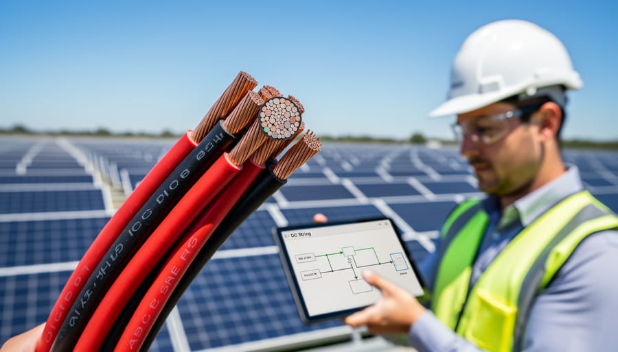
DC vs. AC: Why the Terminology Matters
In photovoltaic systems, the terminology “3-phase conductor” can create significant confusion because DC electrical systems fundamentally operate differently from AC systems. Understanding this distinction is essential for proper system design and professional communication within the solar industry.
Direct current systems utilize positive and negative conductors to complete electrical circuits. Unlike alternating current systems, DC power flows continuously in one direction, from the positive terminal through the load to the negative terminal. There are no true phases in DC circuits—the concept of phase refers specifically to the timing relationship between alternating voltage waveforms, which does not exist in direct current applications.
In AC electrical systems, three-phase configurations use three conductors carrying alternating currents offset by 120 degrees, plus a neutral conductor. This phase relationship enables efficient power transmission and balanced loads in utility grids and large-scale electrical distribution. The term “phase” in this context has precise technical meaning related to sinusoidal waveforms.
The confusion arises in photovoltaic contexts when installers encounter large-scale solar arrays with multiple DC strings feeding into three-phase inverters. Some professionals mistakenly apply AC terminology to DC circuits, referring to multi-conductor DC cable assemblies as “3-phase conductors.” This misnomer typically describes DC cables containing multiple insulated conductors within a single jacket, used for connecting multiple strings or managing positive, negative, and grounding conductors together.
For aspiring photovoltaic professionals, maintaining precise terminology is crucial for safety, regulatory compliance, and effective collaboration with electrical engineers and inspectors. When discussing DC string conductors, always specify positive and negative polarities rather than phases, ensuring clarity in technical documentation and installation specifications.
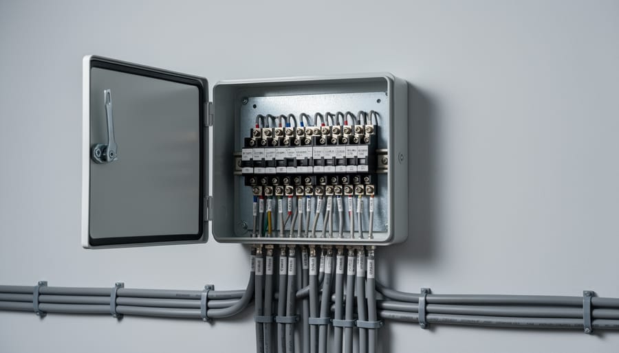
Multi-String Conductor Arrangements
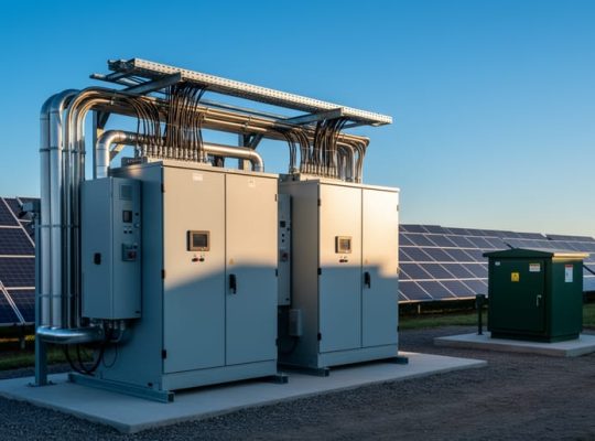
In photovoltaic systems with multiple DC strings connected to a single inverter input, conductor sizing requirements become more complex than single-string configurations. When parallel strings combine at junction boxes or combiner boxes, the cumulative current increases proportionally, requiring appropriately sized conductors to handle the aggregate amperage safely.
The fundamental principle governing multi-string arrangements involves calculating the total short-circuit current from all parallel-connected strings. Each string contributes its individual short-circuit current rating, and the combined conductor must accommodate the sum of these currents multiplied by the National Electrical Code’s continuous current factor of 1.25. For installations with additional temperature or conduit fill correction factors, the conductor ampacity requirements increase accordingly.
Modern DC string design typically employs tiered conductor sizing, where individual string conductors maintain standard sizing based on module specifications, while home-run conductors from combiners to inverters require larger cross-sectional areas. This approach optimizes material costs while ensuring code compliance and system safety.
Combiner boxes serve as critical junction points where multiple strings transition to larger conductors. The output conductor from a combiner box must accommodate the maximum combined current while accounting for voltage drop considerations across the distance to the inverter. Installation designers should calculate voltage drop at both maximum power point and short-circuit conditions to verify conductor adequacy.
Professional installations often utilize color-coded conductors and clear labeling systems to distinguish positive and negative polarities across multiple string configurations, enhancing safety during maintenance operations and troubleshooting procedures.
DC String Sizing Fundamentals for Solar Installations
Calculating String Voltage Parameters
Accurate voltage calculations form the foundation of safe and efficient DC string design in photovoltaic systems. Understanding how various parameters affect string voltage ensures compliance with equipment ratings and maximizes system performance.
The maximum system voltage calculation begins with the module’s open-circuit voltage (Voc) at Standard Test Conditions, typically found on the manufacturer’s datasheet. However, modules generate higher voltages in cold conditions, making temperature correction essential. The National Electrical Code requires calculating maximum voltage at the lowest expected ambient temperature for the installation site, typically using a record low temperature or the 2-percent minimum design temperature.
Temperature coefficients, expressed as a percentage per degree Celsius, indicate how voltage changes with temperature variations. Most crystalline silicon modules have negative voltage temperature coefficients ranging from -0.30 to -0.35 percent per degree Celsius. To calculate maximum voltage, multiply the module’s Voc by the temperature coefficient factor: [1 + (coefficient × temperature difference)]. For example, a module with 40V Voc and -0.35 percent/°C coefficient at -10°C yields approximately 45.6V maximum.
Voltage drop calculations ensure adequate power delivery to inverters. Conductors carrying DC current experience resistive losses proportional to current flow and conductor length. The acceptable voltage drop typically ranges from 1 to 3 percent of the total system voltage. Calculate voltage drop using the formula: VD = 2 × K × I × L / CM, where K represents the conductor material constant, I is current, L is one-way distance, and CM denotes circular mil area.
These calculations directly influence conductor sizing decisions, as undersized conductors increase voltage drop and reduce system efficiency, while oversized conductors unnecessarily increase installation costs without proportional benefits.
Determining String Current Requirements
Proper conductor sizing in photovoltaic systems requires accurate calculation of string current requirements to ensure system safety and optimal performance. The process begins with determining the short-circuit current (Isc), which represents the maximum current a solar module can produce under ideal conditions when its output terminals are short-circuited. This value is typically provided on the module’s specification sheet and serves as the foundation for all subsequent calculations.
For standard temperature conditions (STC), module manufacturers list the Isc rating at 25°C and 1000 W/m² irradiance. However, real-world conditions often deviate from these parameters. The National Electrical Code (NEC) Article 690.8 requires that Isc be multiplied by 1.25 to account for irradiance variations and environmental factors that can temporarily increase current output beyond rated specifications. This safety factor ensures conductors can handle elevated current levels during high-irradiance conditions.
Maximum power point current (Imp) represents the operating current at which the system generates peak power output. While Imp is lower than Isc, it remains crucial for conductor sizing as it determines continuous operating conditions. Designers must also consider the temperature coefficient of current, which accounts for increased current production at lower module temperatures. In cold climates, modules can generate 10-15% more current than rated values.
When multiple strings connect in parallel, individual string currents combine, requiring conductors rated for the cumulative ampacity. Engineers typically apply an additional 1.25 safety factor to continuous current calculations, resulting in a total multiplier of 1.56 times Isc for conductor ampacity determination. This comprehensive approach ensures conductors maintain adequate capacity throughout varying operational conditions while meeting code requirements.
Conductor Ampacity Design for PV DC Applications
NEC Article 690 Requirements
The NEC Article 690 requirements establish critical standards for photovoltaic conductor sizing that directly impact system safety and performance. Understanding these provisions is essential for proper DC string conductor selection in solar installations.
The fundamental requirement under NEC 690.8(B) mandates that PV system conductors must be sized to carry at least 125% of the maximum circuit current. This safety margin accounts for continuous current operation, which photovoltaic systems experience during peak sun hours. For example, if a string produces a maximum current of 10 amperes, the conductor must accommodate a minimum of 12.5 amperes.
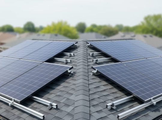
Temperature correction factors add another layer of complexity to conductor sizing. Photovoltaic conductors, particularly those installed in conduit on rooftops or in attics, often experience elevated ambient temperatures exceeding the standard 30°C (86°F) baseline used in ampacity tables. NEC Table 310.15(B)(2)(a) provides temperature correction multipliers that reduce the effective ampacity of conductors in high-temperature environments. In a 50°C ambient temperature, conductors rated for 90°C insulation retain only 82% of their baseline ampacity.
Additionally, conduit fill requirements under NEC 310.15(B)(3)(a) may necessitate further derating when more than three current-carrying conductors occupy the same raceway. Photovoltaic professionals must apply these multipliers sequentially, first adjusting for temperature, then for conduit fill, to determine the final conductor ampacity. This comprehensive approach ensures conductors operate safely within their thermal limits while maintaining code compliance throughout the system’s operational lifetime.
Environmental and Installation Factors
Conductor ampacity ratings don’t exist in isolation—they’re significantly influenced by the environmental conditions where cables are installed. Understanding these factors is essential for proper DC conductor sizing in photovoltaic systems.
Ambient temperature serves as the baseline for all ampacity calculations. Standard ratings typically assume 30°C (86°F) ambient conditions, but rooftop installations regularly experience temperatures exceeding 50°C (122°F) during peak production hours. Each degree above the reference temperature reduces a conductor’s current-carrying capacity, requiring temperature correction factors that can reduce ampacity by 20-30% in extreme environments.
Conduit fill percentage dramatically affects heat dissipation. When multiple conductors share a single conduit, their collective heat generation compounds within the confined space. The National Electrical Code provides adjustment factors based on the number of current-carrying conductors, with derating increasing substantially beyond three conductors. For solar installations with numerous DC strings converging at a combiner location, proper conduit sizing becomes critical to maintain adequate ampacity.
Insulation type selection depends on exposure conditions and maximum operating temperatures. Common PV-rated insulations include THWN-2 (90°C wet or dry), RHW-2 (90°C wet), and USE-2 (90°C wet, specifically rated for underground service). Direct burial applications require moisture-resistant ratings, while exposed rooftop runs demand UV-resistant jackets and higher temperature tolerances.
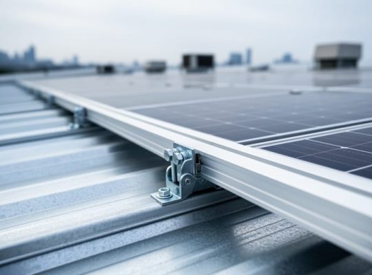
Installation method matters considerably—free air installations dissipate heat more effectively than buried or enclosed runs, allowing higher current capacity for identical conductor sizes. Proper derating ensures conductors operate safely within their thermal limits throughout the system’s operational lifetime.
Selecting the Right Conductor Size
Proper conductor sizing for photovoltaic DC systems requires careful consideration of wire gauge, material composition, and ampacity requirements. The American Wire Gauge (AWG) system standardizes conductor sizes, with smaller numbers indicating larger wire diameters. For high-current applications exceeding AWG 1/0, the industry uses kcmil (thousand circular mils) measurements.
When selecting between copper and aluminum conductors, several factors warrant consideration. Copper offers superior electrical conductivity, requiring smaller wire sizes for equivalent current-carrying capacity. Aluminum conductors provide a cost-effective alternative, particularly for longer runs, though they necessitate larger gauge sizes to achieve comparable ampacity. Aluminum’s lighter weight simplifies installation in roof-mounted applications, but requires specialized termination techniques and anti-oxidant compounds to prevent connection degradation.
Ampacity tables, published by the National Electrical Code and conductor manufacturers, serve as essential references for determining appropriate wire sizes. These tables account for ambient temperature, insulation type, and installation method. For DC photovoltaic applications, designers must apply temperature correction factors and conductor bundling adjustments to ensure safe operation under maximum solar irradiance conditions.
The standard design practice multiplies the calculated circuit current by 1.25 to establish the minimum ampacity requirement, providing adequate safety margin for continuous operation. Multi-string configurations demand careful evaluation of combined currents at junction points, ensuring upstream conductors accommodate accumulated amperage from parallel-connected strings. Academic research through university partnerships continues advancing conductor selection methodologies, improving system reliability while optimizing material costs for large-scale solar installations.
Combining Multiple Strings: Conductor Design Considerations
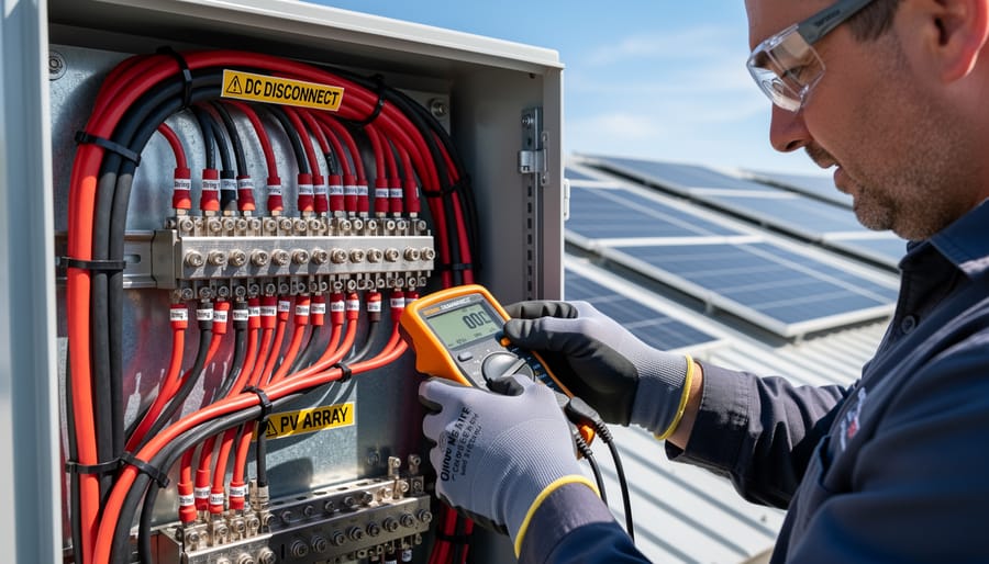
Combiner Box and Homerun Conductor Sizing
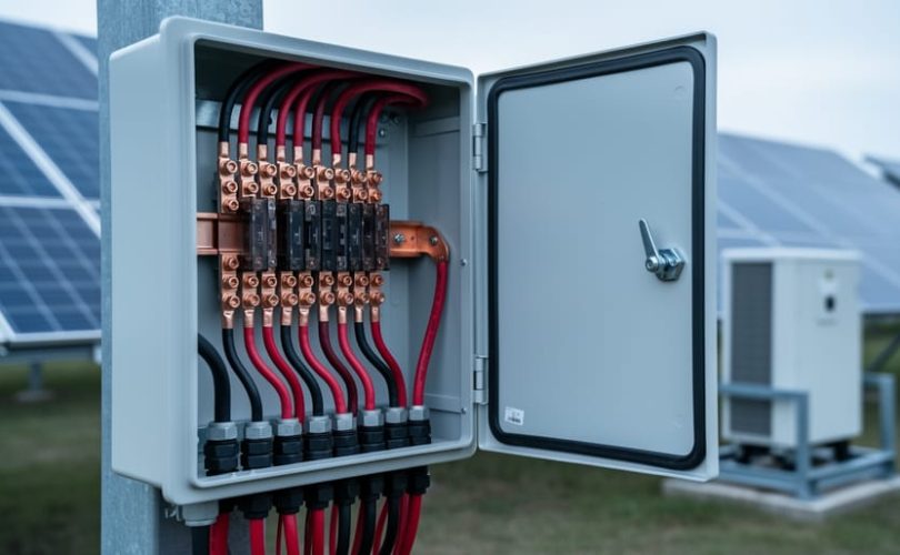
When multiple PV strings combine their current output, conductor sizing must account for the cumulative amperage flowing through shared conductors. This critical junction typically occurs at the combiner box, where individual string conductors merge into larger homerun conductors that transmit power to the inverter.
The fundamental sizing principle requires calculating the combined maximum circuit current from all connected strings. For instance, if four strings each produce 10 amperes of short-circuit current, the homerun conductor must safely carry 40 amperes. Applying the National Electrical Code requirement of 125 percent continuous load rating, the conductor ampacity must meet or exceed 50 amperes under standard temperature and conduit fill conditions.
Proper combiner box design incorporates overcurrent protection devices sized appropriately for both the incoming string conductors and outgoing homerun conductors. Temperature correction factors and conduit adjustment factors frequently necessitate upsizing conductors beyond initial calculations, particularly when multiple current-carrying conductors share raceways in high-temperature environments.
Voltage drop considerations become increasingly important for homerun conductors due to their extended length from the array to the inverter location. Industry best practices recommend limiting voltage drop to 2 percent or less to maintain system efficiency. This often requires conductors significantly larger than ampacity calculations alone would indicate.
Educational programs through university partnerships emphasize the importance of coordinating conductor sizing with overcurrent protection, ensuring safe and efficient power transmission from the array to conversion equipment while maintaining code compliance and optimizing system performance.
Parallel String Configuration Impacts
When multiple photovoltaic strings connect in parallel before reaching the combiner box or inverter, understanding current summation becomes critical for proper conductor sizing and system protection. Each parallel string contributes its short-circuit current to the combined total, requiring conductors rated to handle this cumulative amperage safely.
In parallel DC string configurations, the combined current equals the sum of individual string currents. For example, three parallel strings each producing 10 amperes will generate a total of 30 amperes flowing through the common conductor. National Electrical Code Article 690 requires that conductors handling combined currents be sized at least 125% of the calculated short-circuit current, with an additional 25% safety factor when three or more current sources operate simultaneously.
Unbalanced conditions present particular challenges in parallel string designs. When strings experience different levels of shading, soiling, or module degradation, current imbalances occur. These imbalances can cause reverse current flow in underperforming strings, potentially exceeding conductor ratings and creating safety hazards. Proper system design incorporates string-level monitoring and individual overcurrent protection devices to detect and mitigate these conditions.
Overcurrent protection device selection requires careful consideration of both continuous and fault current scenarios. Fuses or circuit breakers must coordinate with conductor ampacity while providing adequate protection against ground faults and short circuits. The protection device rating should fall between the conductor’s ampacity and the maximum fault current, ensuring that abnormal conditions trigger protective action before conductor damage occurs. Modern photovoltaic installations increasingly utilize DC-rated circuit breakers offering enhanced protection and easier maintenance compared to traditional fuse-based systems.
Common Design Mistakes and How to Avoid Them
Undersizing Conductors
Undersizing conductors in photovoltaic DC string applications poses significant safety and performance risks that can compromise entire solar installations. When conductors lack adequate ampacity for the current they must carry, several critical issues emerge: excessive voltage drop reduces system efficiency, insulation degradation accelerates due to thermal stress, and fire hazards increase substantially as conductors operate beyond their temperature ratings.
The National Electrical Code requires conductors to handle 125 percent of the maximum system current, but prudent design often incorporates additional safety margins. For DC string circuits, calculate the string short-circuit current, then multiply by 1.25 to establish the minimum conductor ampacity. However, environmental factors demand further consideration—elevated ambient temperatures in attic spaces or rooftop conduits can reduce conductor ampacity by 20 to 30 percent. Temperature correction factors and conduit fill adjustments must be applied systematically.
Professional installers verify their calculations using ampacity tables from NEC Article 310, cross-referencing conductor material, insulation type, and installation conditions. Digital design tools can streamline these calculations while reducing human error. Remember that undersizing represents a false economy; the modest cost difference between adequate and inadequate conductors pales compared to system failures, reduced energy production, or potential fire incidents. Proper conductor sizing protects both investment and safety throughout the system’s operational lifetime.
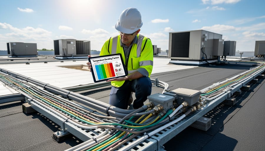
Ignoring Temperature Derating
A frequently overlooked factor in DC conductor sizing is temperature derating, which becomes critically important in hot climates and rooftop installations. Conductors operating in elevated ambient temperatures experience reduced current-carrying capacity, as their insulation rating degrades with heat exposure. The National Electrical Code mandates temperature correction factors that can reduce ampacity by 20-40% when ambient temperatures exceed standard rating conditions of 30°C (86°F). Rooftop conduit installations, particularly those exposed to direct sunlight, can experience temperatures exceeding 70°C (158°F), necessitating significant derating adjustments. Failure to apply these correction factors leads to undersized conductors that operate beyond safe thermal limits, accelerating insulation degradation and creating potential fire hazards. For multi-string installations where conductor sizing already requires careful calculation, ignoring temperature derating compounds the risk of system failure and code violations.
Voltage Drop Oversights
Excessive voltage drop in three-phase conductor systems significantly undermines photovoltaic installation efficiency by reducing power delivery to inverters and increasing resistive losses. For optimal performance, the National Electrical Code recommends limiting voltage drop to 3% for branch circuits and 5% total for combined feeder and branch circuits. In DC string configurations, proper voltage drop calculations account for conductor length, wire gauge, current capacity, and operating temperature. Calculate voltage drop using the formula: VD = (2 × K × I × L) / CM, where K represents the conductor material constant, I is current in amperes, L equals one-way conductor length in feet, and CM denotes circular mil area. University research collaborations have demonstrated that undersized conductors can reduce system output by 2-4% annually, directly impacting return on investment for solar installations.
Proper conductor sizing in photovoltaic DC string design represents a fundamental pillar of system safety, performance optimization, and regulatory compliance. As this guide has demonstrated, selecting appropriate conductors requires careful consideration of multiple factors including continuous current ratings, temperature correction, conduit fill adjustments, and voltage drop calculations. While the terminology around three-phase conductors can initially cause confusion in DC applications, understanding the distinction between AC distribution systems and DC string wiring clarifies the path toward correct design decisions. The consequences of undersized conductors extend beyond mere inefficiency—they pose genuine safety hazards including fire risk, equipment damage, and premature system failure.
For aspiring photovoltaic professionals and those seeking to deepen their technical expertise, Mose Solar offers comprehensive educational resources developed through collaborative partnerships with leading universities. These programs provide structured learning pathways that transform theoretical knowledge into practical competency, equipping individuals with the skills necessary to navigate complex conductor sizing scenarios confidently. Whether you are an installer, designer, or renewable energy enthusiast, investing time in understanding these fundamental principles will enhance your professional capabilities and contribute to the broader advancement of safe, efficient solar energy systems. The solar industry’s continued growth demands professionals who combine technical precision with commitment to excellence.