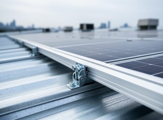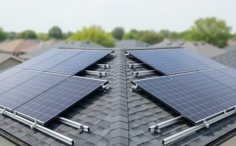
B-roof configurations represent one of the most challenging structural scenarios in photovoltaic installations, demanding precise engineering calculations and specialized mounting strategies to ensure system integrity and longevity. This roof geometry, characterized by two sloped surfaces meeting at a central ridge with valleys at the eaves, creates unique load distribution patterns that differentiate it fundamentally from standard gable or flat roof applications.
Understanding B-roof mechanics requires mastering the interplay between wind uplift forces, snow accumulation in valley regions, and the asymmetric load paths that transfer structural demands through rafters to supporting walls. Professional installers must account for increased stress concentrations at ridge and valley intersections, where mounting hardware experiences magnified forces compared to uniform roof planes. The structural complexity intensifies when integrating photovoltaic arrays, as panel placement directly affects load distribution and requires careful consideration of attachment point spacing, rail orientation, and ballast requirements.
Modern B-roof installations demand proficiency in advanced load calculation methodologies, including ASCE 7 wind pressure coefficients specific to complex geometries and snow drift analysis for valley accumulation zones. Engineers must evaluate rafter capacity, sheathing strength, and connection adequacy while addressing thermal expansion, seismic considerations, and long-term material degradation. This technical foundation becomes essential whether designing commercial-scale projects or residential applications, as improper mounting strategies can compromise both structural safety and system performance. Mastering B-roof installations positions professionals to handle the industry’s most technically demanding projects while ensuring compliance with evolving building codes and engineering standards.
What Is B-Roof in Solar PV Mounting Systems?
Structural Characteristics of B-Roof Systems
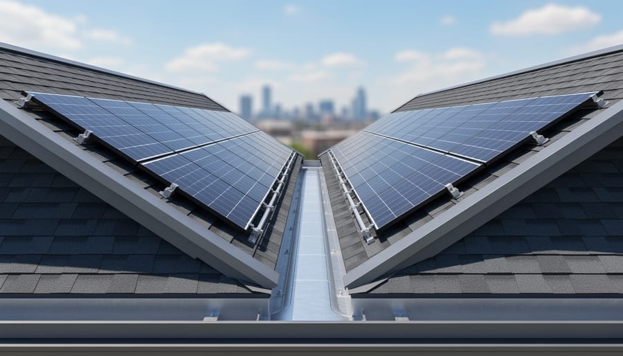
B-roof systems, also known as duo-pitch or gable roofs, represent one of the most common residential and commercial roofing structures encountered in photovoltaic installations. These structures feature two sloped planes that meet at a central ridge, creating the characteristic triangular profile when viewed from the gable end. The defining structural characteristic lies in the symmetrical or asymmetrical arrangement of opposing roof surfaces, each supported by a framework of rafters, trusses, or engineered lumber systems.
The slope angles of B-roof structures typically range from 15 to 45 degrees, though variations exist based on regional building codes, climate considerations, and architectural preferences. Steeper slopes facilitate water drainage and snow shedding, while lower pitches may offer more usable surface area for solar array placement. Understanding these slope parameters is essential for calculating appropriate mounting system angles and optimizing photovoltaic energy production.
Load-bearing patterns in B-roof systems distribute forces through multiple pathways. Dead loads, including the permanent weight of roofing materials and solar equipment, transfer vertically through rafters to load-bearing walls. Live loads such as snow accumulation, wind forces, and maintenance personnel create dynamic stress patterns that structural engineers must account for during solar installation design. The rafter configuration, whether utilizing traditional cut rafters, prefabricated trusses, or engineered I-joists, significantly influences attachment point selection and reinforcement requirements.
Critical structural elements include ridge beams, collar ties, and ceiling joists, which work collectively to prevent roof spread and maintain structural integrity. Professional installers must identify these components and verify their load capacity before mounting photovoltaic arrays, ensuring compliance with applicable building standards and manufacturer specifications.
Common Applications in Residential and Commercial Settings
B-roof configurations appear frequently in both residential and commercial buildings, particularly in structures designed with aesthetic considerations or functional requirements for upper-level spaces. In residential settings, these roof profiles commonly characterize modern townhomes, multi-story single-family residences, and contemporary architectural designs where vertical facades transition to sloped roofing elements. The configuration creates distinct living spaces beneath while maintaining traditional pitched roof benefits for weather protection and drainage.
Commercial applications include office buildings, retail complexes, and light industrial facilities where the B-roof design maximizes usable interior volume while providing cost-effective structural solutions. Educational institutions and community centers also frequently incorporate this roofing style to balance architectural appeal with practical space utilization.
Understanding these contexts matters critically for photovoltaic professionals because installation approaches vary significantly based on building use and occupancy patterns. Residential B-roofs may present accessibility challenges and require careful consideration of aesthetic integration with neighborhood characteristics. Commercial installations often involve more complex permitting processes, higher load-bearing capacities, and opportunities for larger system arrays. Additionally, commercial projects typically demand more rigorous engineering documentation and may involve multiple stakeholder approvals. Recognizing these contextual differences enables PV professionals to develop appropriate installation strategies, anticipate project-specific challenges, and deliver solutions that meet both technical requirements and client expectations across diverse building applications.
Load Considerations for B-Roof PV Installations
Dead Loads: Equipment Weight Distribution
Dead loads represent the permanent, static weight that B-roof structures must support throughout their operational lifespan. For photovoltaic installations, these loads primarily consist of PV modules, racking systems, mounting hardware, and associated components. Understanding proper weight distribution is essential for structural integrity and regulatory compliance.
Standard crystalline silicon modules typically weigh between 15 to 25 kilograms each, while mounting rails and hardware add approximately 3 to 5 kilograms per square meter. When calculating total dead loads, professionals must account for the cumulative weight across the entire array footprint. On B-roof configurations, these loads transfer through the racking system to attachment points, which then distribute forces to the underlying rafter structure.
The distribution pattern depends significantly on mounting methodology. Rail-based systems concentrate loads at specific attachment intervals, typically every 1.2 to 1.5 meters along the rafter length. This point-loading requires careful evaluation of individual rafter capacity and potential reinforcement needs. Conversely, ballasted systems spread weight more uniformly but impose higher overall loads that affect the entire roof assembly.
Engineers must verify that the combined dead load remains within the roof’s design capacity, considering existing structural elements and any previous modifications. Proper load distribution analysis prevents overstressing individual rafters while ensuring balanced weight transfer throughout the supporting framework, maintaining long-term structural performance and safety.
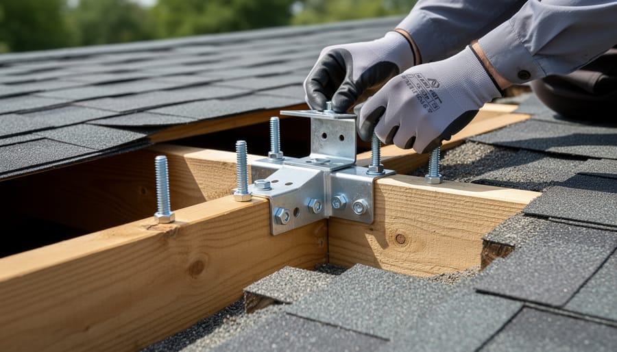
Live Loads: Environmental Forces
B-roof configurations face unique environmental load challenges that require careful analysis during photovoltaic system design. Wind uplift forces present particular concerns for these structures, as the roof geometry creates distinct pressure zones where negative pressures can concentrate. The parapet walls characteristic of B-roofs modify wind flow patterns, potentially increasing uplift forces at roof edges and corners by 40-60% compared to interior zones. Structural engineers must account for these localized pressure coefficients when designing mounting systems, particularly in high-wind regions where code-mandated wind speeds exceed 110 mph.
Snow accumulation patterns on B-roofs differ significantly from sloped configurations. The flat or low-slope geometry allows uniform snow distribution initially, but drifting against mechanical equipment, parapet walls, and array structures creates unbalanced loading conditions. Designers must evaluate drift surcharge loads, which can double the ground snow load in specific areas. Additionally, rain-on-snow scenarios and ice damming potential require drainage system verification to prevent ponding loads that compromise structural integrity.
Maintenance access loads constitute another critical consideration. Service personnel walking across arrays, equipment placement during repairs, and concentrated loads from maintenance platforms must be factored into structural capacity calculations. Building codes typically require minimum 300-pound concentrated live loads for roof access areas, though actual maintenance scenarios may generate higher localized forces. Proper load path analysis ensures both the mounting system and underlying roof structure accommodate these operational demands safely.
Dynamic Load Interactions
B-roof systems experience simultaneous loading from multiple sources that interact in complex ways, requiring careful analysis for safe photovoltaic installations. Building codes mandate specific load combination factors that account for the statistical improbability of all maximum loads occurring simultaneously. The International Building Code prescribes several load combinations, with critical scenarios for rooftop PV including dead load plus live load plus wind, or dead load plus snow plus reduced wind effects. These combinations typically apply factors ranging from 0.5 to 1.6 depending on load permanence and probability. Wind uplift can reduce effective snow loads, while panel arrays may create non-uniform snow accumulation patterns. Dead loads from PV equipment remain constant but combine additively with variable loads. Engineers must evaluate each prescribed combination to identify the governing case for structural adequacy. Dynamic effects introduce additional considerations, as wind-induced vibrations can amplify stresses in mounting hardware. Temperature cycling causes differential expansion between roof materials and aluminum rails, creating fatigue loading over the system’s 25-year design life. Understanding these interaction principles ensures PV professionals design resilient installations that maintain structural integrity under realistic multi-hazard scenarios encountered throughout operational service.
Mounting System Selection for B-Roof Configurations
Rafter-Mount vs. Distributed Attachment Systems
When selecting an attachment system for B-roof photovoltaic installations, professionals must understand the fundamental differences between rafter-mount and distributed attachment approaches, as each method presents distinct structural implications and performance characteristics.
Rafter-mount systems concentrate load transfer at specific structural members, connecting mounting rails directly to roof rafters or trusses. This approach offers exceptional load-bearing capacity and simplifies engineering calculations, making it particularly suitable for heavier crystalline silicon arrays or installations in high-wind regions. However, rafter-mount systems require precise rafter location, potentially limiting panel layout flexibility and demanding careful waterproofing at each penetration point.
Distributed attachment systems spread loads across multiple connection points, often utilizing shared rails that attach to roof decking or purlins at regular intervals. This method proves advantageous for B-roof configurations where rafter spacing doesn’t align with optimal panel layouts or where load distribution across a broader surface area reduces stress concentrations. Distributed systems typically enable faster installation and greater design adaptability, though they require more comprehensive structural analysis to verify decking adequacy.
The choice between these approaches depends on several factors: existing roof structural capacity, B-roof geometry, local wind and snow loads, and panel specifications. Many modern installations combine both methods, using rafter-mounted primary rails with distributed secondary attachments. This hybrid approach balances structural integrity with installation efficiency, similar to how integrated electrical system design requires coordinating multiple components for optimal performance. Professional engineers should conduct site-specific structural assessments to determine the most appropriate attachment strategy for each B-roof application.
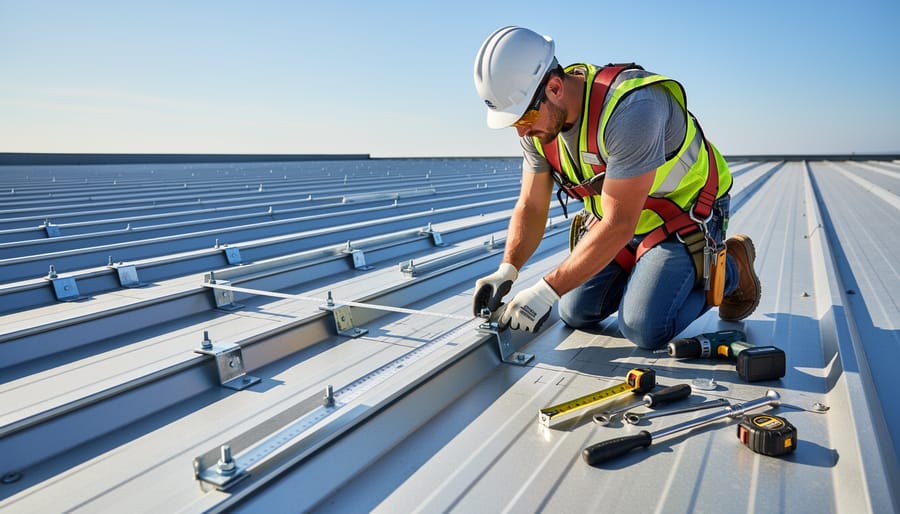
Ballasted Systems and B-Roof Limitations
Ballasted mounting systems offer a non-penetrating installation method for rooftop photovoltaic arrays, making them particularly attractive for B-roof structures where maintaining membrane integrity is essential. These systems rely on gravitational force and strategically distributed weight to secure solar panels without drilling into the roof substrate. However, B-roof structures present specific limitations that require careful evaluation before selecting this approach.
The primary consideration for ballasted systems on B-roofs involves structural load capacity. Standard B-roof designs typically support live loads between 20-30 pounds per square foot, though actual capacity varies based on structural specifications and building codes. Ballasted systems can add 3-8 pounds per square foot depending on configuration, ballast material, and local wind exposure categories. Engineers must verify that the combined dead load of the mounting system, modules, and ballast, plus applicable live loads including snow and maintenance personnel, remains within the roof’s structural capacity.
Weight distribution patterns also merit attention on B-roof structures. Unlike reinforced concrete roofs, the steel decking and bar joist construction common in B-roofs creates specific load paths. Concentrated loads from ballast blocks must align with structural members to prevent localized deflection or deck failure. Professional structural analysis becomes indispensable when existing documentation inadequately defines load-bearing capacity.
Wind uplift calculations further complicate ballasted installations on B-roofs. The relatively lightweight nature of steel decking compared to concrete substrates may require additional ballast to counteract aerodynamic forces, potentially exceeding structural limits. In high-wind zones or buildings exceeding certain height thresholds, mechanically attached systems often prove more viable than ballasted approaches, despite the penetration requirements they introduce to the roofing membrane.
Structural Engineering Calculations for B-Roof PV Systems
Load Path Analysis
Understanding load path analysis is fundamental for safe and compliant B-roof photovoltaic installations. The load transfer mechanism begins at the PV modules, where environmental forces including wind uplift, snow accumulation, and self-weight create stress points that must be systematically managed through the structural system.
Loads first concentrate at the module frames, transferring through mid-clamps and end-clamps into the mounting rails. These rails, typically aluminum extrusions, distribute forces longitudinally before channeling them to attachment points. The attachment hardware—whether brackets, L-feet, or specialized connectors—serves as the critical interface between the mounting system and the roof structure itself.
From attachments, loads transmit directly into the rafters or roof beams. This connection point demands careful engineering consideration, as B-roofs lack the continuous deck support found in conventional designs. Each attachment must anchor into solid structural members capable of resisting both downward gravitational loads and potentially substantial wind uplift forces.
The rafters then convey these accumulated loads through the roof assembly into load-bearing walls and foundation systems. Proper load path analysis requires verification at every transition point, ensuring no single component becomes overstressed. Engineers must account for load combinations, safety factors, and building code requirements throughout this chain.
This systematic approach connects with broader system considerations, including DC string design planning, ensuring holistic project integration from structural mounting through electrical infrastructure.
Tributary Area and Spacing Calculations
Proper spacing of attachment points on B-roofs requires careful analysis of tributary areas, which represent the roof surface area supported by each mounting location. Begin by identifying rafter locations through direct measurement or reviewing building plans, as these structural members must support all photovoltaic system loads. Industry standards typically recommend attachment spacing between 24 to 48 inches on center, depending on module dimensions and local load requirements.
Calculate the tributary area by multiplying the distance between adjacent rafters by the spacing between mounting rails. For example, rafters spaced 24 inches apart with rails every 48 inches create a tributary area of 8 square feet per attachment point. This area determines the concentrated load each connection must withstand, including dead loads from equipment weight and live loads from wind, snow, and maintenance activities.
Load distribution becomes particularly critical on B-roofs where existing structural capacity may be limited. Installers should verify that calculated loads fall within acceptable ranges specified by structural engineers or building codes. When tributary areas exceed structural capacity, reduce attachment spacing or redistribute loads through additional support members to ensure system integrity and occupant safety.
When to Require Structural Reinforcement
Several critical indicators signal when B-roof structures require reinforcement before solar panel installation. Visible sagging or deflection in roof beams exceeds acceptable tolerances and demands immediate structural evaluation. Cracks in load-bearing members, deteriorated wood components, or corroded steel framing compromise structural integrity and must be addressed prior to adding photovoltaic arrays.
Age plays a significant role—buildings constructed before modern building codes may lack adequate load capacity for contemporary PV systems. Professional structural assessments should be mandatory when original construction documentation is unavailable or when existing loads already approach design limits.
Load calculations revealing that combined dead loads, live loads, and proposed PV equipment exceed 90% of the roof’s rated capacity necessitate strengthening measures. Water damage, pest infestation, or previous unauthorized modifications further compromise structural reliability. These conditions require remediation aligned with PV design principles and local engineering standards before installation proceeds, ensuring both system performance and occupant safety throughout the installation’s service life.
Code Compliance and Safety Standards
International Building Code (IBC) Requirements
The International Building Code establishes comprehensive structural requirements that directly impact photovoltaic installations on B-roof configurations. Chapter 15 of the IBC specifically addresses roof assemblies and rooftop structures, mandating that all PV mounting systems comply with minimum design loads for wind, snow, seismic activity, and dead loads. For B-roof applications, engineers must account for tributary area calculations that determine load distribution patterns across the structural framework.
IBC Section 1504 requires PV mounting systems to maintain proper drainage and not compromise the roof’s weather-resistant barrier. Ballasted systems on B-roofs must meet uplift resistance standards outlined in ASCE 7, with particular attention to parapet height and edge zone classifications. The code mandates structural calculations certified by licensed professional engineers for installations exceeding specific weight thresholds, typically 4-5 pounds per square foot including equipment.
Fire classification requirements under IBC Chapter 15 also apply to rooftop PV arrays, necessitating appropriate setbacks and access pathways for emergency responders. Compliance with IBC provisions ensures that B-roof PV installations maintain structural integrity throughout their operational lifespan while meeting local jurisdiction amendments to the base code.
ASCE 7 Wind and Snow Load Standards
The American Society of Civil Engineers (ASCE) 7 standard provides the foundational framework for calculating wind and snow loads on photovoltaic installations, including B-roof configurations. This comprehensive standard addresses the unique aerodynamic challenges that rooftop solar arrays present, particularly on structures with complex roof geometries or varying pitch angles.
For B-roof PV systems, ASCE 7-22 requires careful consideration of wind uplift forces, which can vary significantly based on roof zone classification. Arrays positioned near roof edges, ridges, or corners experience higher wind pressures compared to interior field zones. Engineers must account for these location-specific factors when designing mounting systems and selecting appropriate attachment methods.
Regional variations play a critical role in load calculations. Coastal installations face substantially higher wind design pressures, while northern climates demand robust snow load assessments. Ground snow loads vary dramatically across the United States, from negligible amounts in southern regions to over 100 pounds per square foot in mountainous areas. The standard requires engineers to evaluate both balanced and unbalanced snow accumulation scenarios, which can create asymmetric loading conditions on solar arrays. These considerations directly influence structural reinforcement requirements and mounting hardware specifications for safe, compliant installations.
Common Design Mistakes and How to Avoid Them
Underestimating Wind Uplift on Sloped Surfaces
B-roof configurations present unique aerodynamic challenges that many installers overlook during initial design phases. The geometric transition between the two roof planes creates concentrated wind pressure zones, particularly along ridge lines and slope transitions, where uplift forces can exceed standard calculations by 30-50%. These pressure differentials result from wind acceleration over the building envelope, generating negative pressures that attempt to lift solar arrays from their mounting points.
The steeper upper slope of a B-roof amplifies these effects, creating a venturi effect that intensifies wind velocity and corresponding uplift forces. Engineers must account for the local wind exposure category, roof height, and the specific angle relationship between both slopes when calculating design loads. Standard wind load tables often fail to capture these nuanced pressure distributions, leading to undersized mounting hardware or inadequate ballasting strategies.
Proper assessment requires computational fluid dynamics modeling or consultation with wind engineering specialists for commercial-scale installations. Field measurements have demonstrated that corner zones and ridge transitions experience peak uplift forces requiring reinforced attachment methods. Professional installers should always reference ASCE 7 wind load provisions specific to complex roof geometries and incorporate safety factors that address the unique aerodynamic profile of B-roof structures. This approach ensures structural integrity throughout the system’s operational lifespan.
Inadequate Waterproofing at Penetration Points
Penetration points represent one of the most vulnerable areas in B-roof photovoltaic installations, where mounting hardware breaches the roofing membrane and creates potential pathways for water intrusion. Unlike ballasted systems that minimize roof penetrations, B-roof configurations typically require multiple anchor points to secure mounting rails and frames, making proper waterproofing essential for long-term system performance.
The primary challenge stems from the inherent conflict between structural requirements and waterproofing integrity. Each mounting bracket or anchor bolt creates a discontinuity in the roof’s protective barrier, and improper sealing can lead to leaks, structural degradation, and costly repairs. Industry best practices recommend using multi-layered waterproofing approaches that combine mechanical fasteners with appropriate sealants and flashing systems designed for the specific roofing material.
For B-roof installations, contractors should employ manufacturer-approved mounting systems that include integrated waterproofing components such as EPDM boots, metal flashing plates, and compatible sealants rated for UV exposure and temperature cycling. The installation sequence matters significantly—flashing should be properly lapped under upper roofing materials and over lower sections to direct water away from penetration points. Regular post-installation inspections, particularly after severe weather events, help identify potential seal failures before they cause interior damage. Collaboration between roofing professionals and PV installers during the design phase ensures compatibility between mounting requirements and waterproofing specifications, reducing the risk of system compromises.
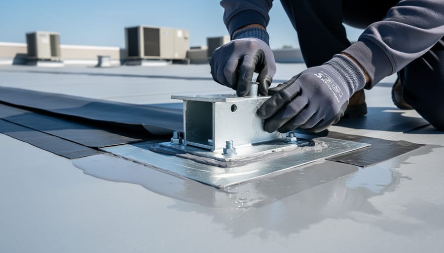
Educational Resources for Mastering B-Roof Design
Professional development in B-roof structural design requires systematic education combining theoretical knowledge with practical application. Mose Solar addresses this need through comprehensive training programs developed in collaboration with leading universities and industry partners.
Our educational initiatives encompass multiple learning pathways tailored to different experience levels. Entry-level professionals benefit from foundational courses covering structural load calculations, material properties, and mounting system fundamentals specific to B-roof configurations. These programs integrate PV system engineering principles with hands-on design exercises, enabling participants to confidently approach real-world projects.
Advanced certification tracks delve into complex topics including wind uplift analysis, seismic considerations, and thermal expansion management in B-roof applications. University partnerships ensure curriculum content reflects current building codes, engineering standards, and emerging best practices. Participants gain access to proprietary design tools, structural modeling software, and extensive case study libraries drawn from actual installations.
Continuing education webinars and technical workshops keep professionals updated on evolving regulations, innovative mounting technologies, and efficiency optimization strategies. These sessions feature industry experts discussing recent B-roof projects, addressing common design challenges, and sharing lessons learned from field implementations.
By investing in structured educational resources, installers and engineers develop the competencies needed to execute B-roof projects safely, efficiently, and in full compliance with structural requirements, ultimately advancing the solar industry’s professional standards.
Proper B-roof design and implementation represent foundational pillars of successful photovoltaic installations that cannot be compromised. The structural integrity of solar mounting systems directly impacts system longevity, safety, and performance throughout their operational lifespan. As the renewable energy sector continues its rapid expansion, the demand for skilled professionals who understand the nuances of rooftop structural considerations will only intensify.
For aspiring PV professionals, mastering B-roof principles opens pathways to meaningful careers in sustainable energy. This knowledge extends beyond theoretical understanding—it requires hands-on experience, continuous learning, and commitment to industry best practices. Educational institutions and industry organizations increasingly offer specialized training programs that address these technical competencies, bridging the gap between academic knowledge and practical application.
The consequences of inadequate structural planning extend far beyond project delays or cost overruns. Compromised installations pose safety risks to building occupants, installers, and the surrounding community while potentially undermining public confidence in solar technology. Every professional in this field bears responsibility for upholding rigorous standards that protect both people and investments.
Moving forward, embrace opportunities for professional development through certifications, workshops, and collaborative learning environments. Remember that structural integrity in solar installations is never optional—it is the essential foundation upon which the renewable energy transition depends.