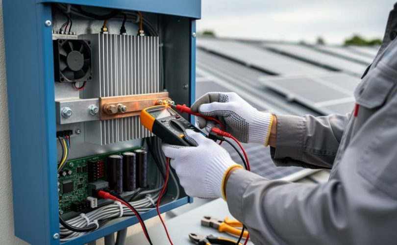
Diagnose inverter malfunctions by checking error codes displayed on the LCD panel or monitoring system—these codes pinpoint specific component failures such as ground faults, DC overvoltage, or communication errors. Test DC input voltage using a multimeter to verify your solar array delivers proper voltage levels; readings significantly below nameplate specifications indicate upstream wiring issues or panel degradation rather than inverter problems.
Measure AC output voltage and frequency at the inverter terminals to confirm grid-compliant power delivery; deviations exceeding ±10% for voltage or ±0.5Hz for frequency signal internal power conversion failures requiring immediate attention. Inspect thermal management systems including cooling fans, heat sinks, and ventilation pathways, as 60% of premature inverter failures stem from inadequate temperature regulation in hot climates or enclosed installations.
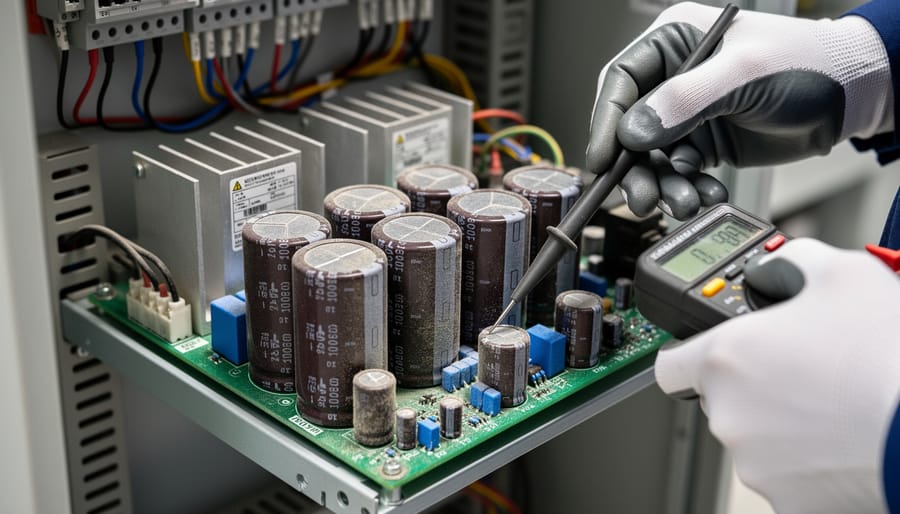
Replace failed capacitors—the most common repair scenario—by identifying bulging or leaking electrolytic components on the circuit board, particularly in the DC bus and power factor correction stages. Verify IGBT module integrity using a semiconductor tester, as these switching devices account for approximately 25% of inverter failures and often degrade gradually before complete failure.
Document baseline performance metrics including conversion efficiency, daily energy production, and operating temperatures to establish normal parameters for your specific installation. This data enables early detection of performance drift that precedes catastrophic failures, allowing proactive intervention before complete system shutdown occurs. Professional certification programs through university partnerships provide structured training in advanced diagnostic techniques and emerging repair methodologies for photovoltaic professionals seeking specialized expertise.
Understanding Solar Inverter Function and Common Failure Points
The Role of Inverters in Energy Conversion
Solar inverters perform three critical functions that determine system performance and longevity. Understanding these operations is essential for effective diagnostics and repair.
The primary function involves DC to AC conversion, transforming direct current from photovoltaic panels into alternating current compatible with household appliances and grid infrastructure. This conversion process relies on power electronics components including insulated gate bipolar transistors (IGBTs) or metal-oxide-semiconductor field-effect transistors (MOSFETs) that switch rapidly to create AC waveforms. Conversion efficiency typically ranges from 95% to 98% in quality inverters, with losses manifesting as heat that must be properly dissipated.
Maximum power point tracking (MPPT) optimizes energy harvest by continuously adjusting electrical operating points to extract maximum available power despite varying irradiance and temperature conditions. MPPT algorithms sample voltage and current multiple times per second, making incremental adjustments to maintain peak efficiency. This function becomes particularly critical during partial shading or suboptimal weather conditions.
Grid synchronization ensures inverter output matches utility frequency, voltage, and phase requirements. This function incorporates safety protocols that immediately disconnect during grid disturbances, protecting both equipment and utility workers. Understanding these interconnected functions enables technicians to pinpoint failure modes and implement appropriate repair strategies based on which operational aspect has degraded.
Primary Components Susceptible to Failure
Solar inverters contain several components that experience disproportionately high failure rates due to electrical stress, thermal cycling, and environmental exposure. Understanding these vulnerable elements enables more effective diagnostic approaches and targeted maintenance strategies.
Electrolytic capacitors represent the most failure-prone components in solar inverters, typically degrading after 5-10 years of operation. These devices smooth voltage fluctuations and filter electrical noise, but sustained exposure to elevated temperatures accelerates electrolyte evaporation and capacitance loss. Symptoms include increased ripple voltage, reduced power quality, and eventual complete inverter shutdown. Through collaborative research initiatives with universities, industry professionals have documented that capacitor degradation accounts for approximately 60% of premature inverter failures.
Insulated gate bipolar transistors (IGBTs) and metal-oxide-semiconductor field-effect transistors (MOSFETs) serve as switching devices that convert DC power to AC. These semiconductors fail due to thermal stress, voltage spikes, or manufacturing defects, often manifesting as short circuits or inability to switch properly.
Cooling systems, including fans and heat sinks, experience mechanical wear and debris accumulation. Inadequate thermal management causes cascading failures throughout the inverter by subjecting other components to excessive temperatures.
Printed circuit boards develop solder joint failures, corrosion from moisture intrusion, and trace degradation. Environmental factors such as humidity, salt spray, and temperature extremes accelerate these deterioration processes, particularly in installations lacking proper environmental protection measures.
Environmental and Operational Stress Factors
Solar inverters operate in demanding conditions that significantly impact component longevity and system reliability. Temperature fluctuations represent a primary stress factor, as inverters routinely experience thermal cycling between ambient conditions and elevated operating temperatures. Studies conducted in collaboration with universities demonstrate that every 10°C temperature increase can reduce component lifespan by approximately 50 percent, particularly affecting electrolytic capacitors and power semiconductors.
Humidity creates corrosive environments that compromise circuit boards and electrical connections, accelerating oxidation and short-circuit risks. Coastal installations face heightened vulnerability due to salt-laden moisture. Dust accumulation impedes thermal dissipation by coating heat sinks and blocking ventilation pathways, creating hotspots that precipitate premature failure.
Voltage surges from lightning strikes and grid switching operations subject inverters to transient overvoltages that stress protective components and control circuits. Grid instabilities, including frequency deviations and harmonic distortions, force inverters to operate outside optimal parameters, increasing switching losses and thermal stress. Educational program offerings emphasize comprehensive environmental assessment during installation planning to mitigate these operational challenges and optimize inverter placement within photovoltaic systems.
Diagnostic Approaches for Identifying Inverter Problems
Performance Monitoring and Data Analysis
Modern monitoring systems serve as the first line of defense in detecting inverter problems before complete failure occurs. These platforms continuously track critical performance metrics including DC input voltage, AC output power, operating temperature, and energy conversion efficiency. When inverter performance deviates from expected baselines, monitoring software generates alerts that enable proactive maintenance intervention.
Efficiency drops of 5-10% often indicate developing component degradation, such as failing capacitors or compromised power semiconductors. Unusual output patterns, including intermittent power delivery or voltage fluctuations, typically signal control board malfunctions or unstable grid connections. Most modern inverters also transmit diagnostic error codes that provide specific fault information, from ground fault detection to overheating warnings.
Academic research partnerships have demonstrated that facilities utilizing comprehensive data analysis can reduce unplanned downtime by up to 40%. By establishing performance benchmarks during normal operation, technicians can identify subtle deviations that precede major failures. Regular review of historical data trends enables predictive maintenance scheduling, optimizing repair timing while minimizing production losses and extending overall system lifespan.
Physical Inspection Protocols
Systematic physical inspection forms the foundation of effective solar inverter diagnostics. Begin by conducting a thorough visual examination of the inverter enclosure, looking for signs of physical damage, moisture intrusion, or pest activity. Inspect all electrical connections for looseness, corrosion, or discoloration that may indicate arcing or excessive heat buildup. Pay particular attention to DC input terminals and AC output connections, as these high-current pathways are prone to degradation.
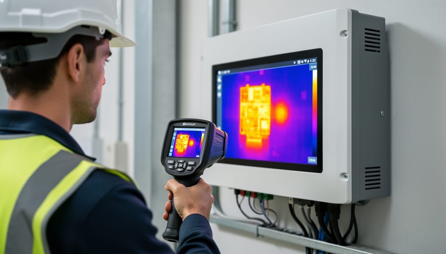
Thermal imaging cameras provide invaluable diagnostic capabilities by revealing temperature anomalies invisible to the naked eye. Scan circuit boards, capacitors, transformers, and switching components during operation to identify hot spots that suggest component stress or impending failure. Temperature differentials exceeding 10°C compared to surrounding components warrant investigation.
Examine capacitors for bulging tops, leaking electrolyte, or discoloration around the base. Check printed circuit boards for burnt traces, cracked solder joints, or charred insulation. Verify that cooling fans operate properly and heat sinks remain free from dust accumulation. Educational programs offered through university collaborations emphasize these inspection techniques as essential preventive maintenance skills for renewable energy professionals.
Electrical Testing Procedures
Systematic electrical testing forms the foundation of accurate inverter diagnostics when troubleshooting solar system problems. Begin with voltage measurements across DC input terminals using a calibrated digital multimeter, comparing readings against the array’s rated open-circuit voltage under standard test conditions. Current measurements at both DC and AC sides reveal performance discrepancies indicating component degradation or circuit faults.
Insulation resistance testing proves essential for identifying potential safety hazards and ground faults. Using a megohmmeter, test between live conductors and ground with the inverter disconnected, ensuring readings exceed 1 megohm per manufacturer specifications. Temperature-corrected measurements provide more accurate assessments of insulation integrity.
Advanced diagnostic equipment, including oscilloscopes and power analyzers, enables waveform analysis and harmonic distortion measurement. These tools identify switching component failures, capacitor deterioration, and control circuit malfunctions. Document all measurements systematically, creating baseline data for future comparison and trend analysis, supporting predictive maintenance programs developed through collaborations with research institutions.
Professional Repair Techniques and Component Replacement
Capacitor and Circuit Board Repairs
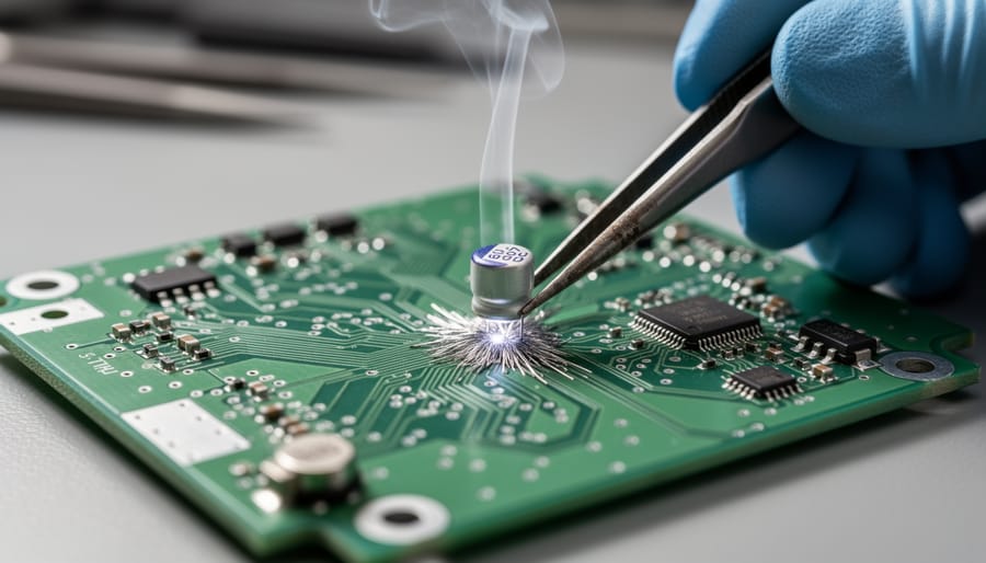
Capacitor failure represents one of the most common inverter malfunctions, particularly in power supply and filtering circuits. When replacing electrolytic capacitors, verify voltage ratings exceed operating specifications by at least 20 percent and ensure temperature ratings match the inverter’s operating environment. Bulging, leaking, or discolored capacitors require immediate replacement to prevent cascading failures in adjacent components.
Circuit board repairs demand proper soldering techniques using temperature-controlled equipment set between 300-350°C for lead-free solder. Cold solder joints, which appear dull and grainy rather than smooth and shiny, compromise electrical conductivity and generate excessive heat. Before resoldering, thoroughly clean oxidized connections with isopropyl alcohol and inspect for corroded traces requiring conductive epoxy repair or copper trace replacement.
For damaged circuit boards exhibiting cracks or delamination, professional-grade photopolymer coatings restore insulation integrity once structural repairs are complete. Many technical training programs through university partnerships now include hands-on circuit board repair modules, preparing photovoltaic professionals for field diagnostics. Document all component replacements with photographs and maintain detailed repair logs, as pattern failures often indicate systemic design limitations or environmental stress factors requiring broader corrective measures beyond individual component replacement.
Power Module and Switching Device Replacement
Replacing power semiconductor devices requires precise technical procedures to maintain inverter reliability and safety. IGBTs (Insulated Gate Bipolar Transistors) and MOSFETs (Metal-Oxide-Semiconductor Field-Effect Transistors) form the core switching components that convert DC to AC power, making their replacement a critical repair operation.
Before replacement, technicians must verify compatible specifications including voltage ratings, current capacity, switching frequency, and thermal characteristics. Using infrared thermography and oscilloscope analysis helps identify failed components within multi-device arrays. Proper desoldering techniques prevent thermal damage to circuit boards, particularly important for surface-mount devices.
Installation demands careful attention to thermal interface materials, ensuring optimal heat transfer between semiconductors and heatsinks. Gate driver circuits must be tested for appropriate voltage levels and timing sequences before energizing new components. Universities collaborating with industry professionals have developed standardized replacement protocols that emphasize ESD (Electrostatic Discharge) protection throughout the procedure.
Post-installation testing should include gate resistance measurements, forward voltage drop verification, and thermal cycling under controlled loads. Educational programs increasingly incorporate hands-on power module replacement training, recognizing this skill’s importance for field technicians. Documentation of component specifications and replacement dates supports future maintenance planning and warranty compliance.
Cooling System and Fan Maintenance
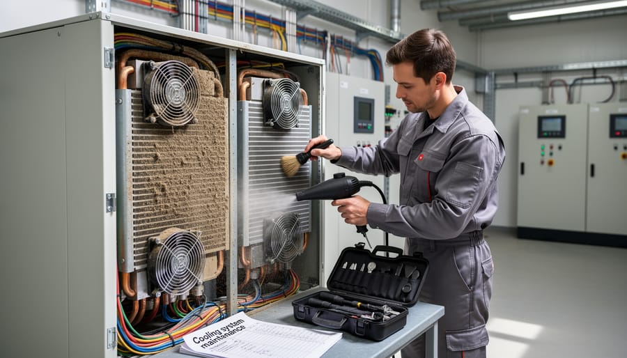
Thermal management components are critical for inverter longevity, as excessive heat accelerates semiconductor degradation and reduces conversion efficiency. Regular inspection of cooling fans should occur quarterly, checking for unusual vibration, bearing noise, or reduced airflow. Debris accumulation on heat sinks significantly impairs thermal dissipation; compressed air cleaning removes dust without component damage. Fan replacement becomes necessary when bearings fail or blade damage occurs, typically using manufacturer-specified models to maintain proper CFM ratings. Heat sink inspection should identify corrosion, loose mounting hardware, or compromised thermal interface materials. Thermal paste reapplication during component replacement ensures optimal heat transfer between power semiconductors and heat sinks. Advanced inverter systems may incorporate liquid cooling circuits requiring leak inspection and coolant condition verification. In collaboration with universities, thermal imaging studies demonstrate that proactive cooling system maintenance can extend inverter operational life by 25-40 percent. Educational programs emphasize establishing temperature monitoring protocols and implementing scheduled maintenance intervals based on environmental conditions, particularly in dusty or high-temperature installations where thermal stress intensifies component wear.
When to Repair vs. Replace: Cost-Benefit Analysis
Determining whether to repair or replace a solar inverter requires systematic evaluation of multiple factors. First, assess repair costs against replacement expenses—repairs exceeding 50% of a new unit’s cost typically favor replacement. Warranty status plays a crucial role; inverters under warranty should be repaired through authorized service providers to maintain coverage. Technology obsolescence must be considered, as inverters older than 8-10 years may lack compatibility with modern monitoring systems and efficiency standards. Evaluate the remaining system lifespan—if your solar panels have 15+ years of productive life remaining, investing in a quality replacement ensures optimal energy harvesting. Additionally, consider efficiency improvements in newer models; contemporary inverters offer superior maximum power point tracking algorithms and reduced conversion losses. For string inverters experiencing repeated failures, transitioning to microinverters or power optimizers may provide better long-term value despite higher upfront costs. Consult with certified technicians who can conduct thermal imaging and performance diagnostics to inform your decision.
Preventive Maintenance Strategies for Inverter Longevity
Scheduled Inspection and Cleaning Routines
Implementing comprehensive preventive maintenance practices significantly extends inverter lifespan and reduces unexpected failures. Schedule quarterly visual inspections to examine all electrical connections for corrosion, looseness, or thermal damage. Tighten terminals to manufacturer-specified torque values and replace corroded connectors promptly.
Ventilation systems require monthly attention in dusty environments and quarterly cleaning otherwise. Use compressed air or soft brushes to remove accumulated debris from cooling fans, heat sinks, and air intake filters. Ensure minimum clearance specifications around the unit remain unobstructed to maintain optimal airflow and thermal performance.
Environmental contaminants demand location-specific attention. Coastal installations need biannual inspections for salt accumulation, while agricultural settings require more frequent cleaning due to pollen and particulate matter. Remove dust, leaves, and insect nests using appropriate cleaning methods that avoid moisture ingress into sealed components. Document all maintenance activities, recording ambient temperature readings and any anomalies observed. This data proves invaluable for identifying degradation patterns and optimizing service intervals based on actual operating conditions rather than generic recommendations.
Firmware Updates and System Optimization
Maintaining current firmware is essential for optimal inverter performance and longevity. Manufacturers regularly release software updates that address identified bugs, enhance grid compatibility standards, and improve energy conversion efficiency. These updates often resolve intermittent operational issues that might otherwise lead to costly hardware repairs or system downtime.
Professional solar technicians should establish routine firmware update schedules, typically checking quarterly for manufacturer releases. Before applying updates, verify compatibility with existing system components and document current configuration settings. Many modern inverters support remote update capabilities, though critical updates may require on-site verification and system testing post-installation.
Updates frequently incorporate new grid support functions mandating compliance with evolving utility interconnection requirements and IEEE standards. Universities collaborating on inverter technology research have documented performance improvements of 2-5% following properly executed firmware updates. Additionally, manufacturers often optimize maximum power point tracking algorithms through software enhancements, directly impacting energy harvest efficiency without hardware modifications.
Always maintain backup configurations and implement updates during low-production periods to minimize operational disruption while ensuring system reliability.
Environmental Protection Measures
Proper installation practices significantly extend inverter lifespan and reduce repair frequency. Position inverters in shaded, well-ventilated locations away from direct sunlight, as excessive heat accelerates component degradation. Install weather-resistant NEMA-rated enclosures when outdoor mounting is unavoidable, ensuring adequate ingress protection against moisture and dust infiltration. Maintain minimum clearance specifications around the unit—typically 12-18 inches on all sides—to facilitate natural convection cooling and prevent thermal stress.
Enhance ventilation through strategic placement of passive vents or active cooling systems in confined spaces. Monitor ambient temperatures regularly, as operating environments exceeding manufacturer specifications can void warranties and reduce semiconductor reliability. Implement comprehensive surge protection at multiple levels: install Type 1 surge protective devices at the service entrance, Type 2 devices at distribution panels, and consider integrated DC surge arrestors for the photovoltaic array. Ground all equipment properly according to National Electrical Code standards, using appropriate conductor sizing and dedicated grounding electrodes. Regular inspections of environmental protection measures should form part of routine maintenance protocols, identifying potential vulnerabilities before they precipitate component failures.
Performance Benchmarking and Record Keeping
Establishing comprehensive baseline performance metrics is essential for effective inverter maintenance. Record key parameters including conversion efficiency, power output, voltage levels, temperature readings, and error codes during optimal operating conditions. Maintain detailed maintenance logs documenting all inspections, repairs, component replacements, and environmental factors affecting performance. This historical data enables trend analysis to identify gradual degradation patterns before they escalate into failures. Digital monitoring systems integrated with predictive maintenance strategies can analyze performance deviations and forecast potential issues. Regular comparison of current metrics against baseline values helps quantify system health and justify proactive interventions. Academic research partnerships demonstrate that systematic record-keeping reduces downtime by up to 40% while extending inverter lifespan through timely corrective actions.
Safety Protocols and Professional Standards in Inverter Repair
Electrical Safety and Lockout/Tagout Procedures
Working with solar inverters requires strict adherence to electrical safety protocols due to inherent high-voltage DC and AC hazards. Before initiating any repair work, technicians must implement comprehensive lockout/tagout (LOTO) procedures to prevent accidental energization. Begin by disconnecting AC power at the circuit breaker, then isolate DC input by opening all combiner box disconnects and PV array switches. Verify zero voltage using a properly rated multimeter on both DC and AC terminals.
Apply physical lockout devices to all disconnection points and attach visible tagout labels indicating maintenance in progress, personnel responsible, and expected completion time. Many educational programs, including those developed through university collaborations, emphasize the critical five-minute waiting period after shutdown to allow capacitors to fully discharge, as residual voltage can exceed 600VDC in string inverters.
Never assume circuits are de-energized without verification. Utilize appropriate personal protective equipment including arc-rated gloves, safety glasses, and insulated tools. Maintain adherence to NFPA 70E standards and manufacturer-specific safety guidelines. Only qualified personnel with demonstrated competency in photovoltaic systems should perform inverter repairs, as improper procedures can result in severe injury or fatality.
Certification Requirements and Manufacturer Guidelines
Professional solar inverter repair requires specific certifications and adherence to manufacturer guidelines to ensure safety, quality, and warranty compliance. Most reputable manufacturers mandate technician certification through their authorized training programs before permitting warranty-covered repairs. These programs typically cover electrical safety protocols, manufacturer-specific diagnostic procedures, and proper component replacement techniques.
The North American Board of Certified Energy Practitioners (NABCEP) offers specialized photovoltaic installer certifications that include inverter maintenance training, though manufacturer-specific credentials remain essential for authorized service work. Many universities now collaborate with industry partners to integrate these certification pathways into their renewable energy curricula, providing students with both theoretical knowledge and practical credentials.
Unauthorized repairs often void manufacturer warranties, which can extend from 5 to 25 years depending on the inverter model. Documentation requirements include maintaining detailed service records, using only approved replacement components, and following prescribed testing procedures. Technicians must also comply with electrical codes and safety standards, including proper lockout-tagout procedures and arc flash protection measures. Continuous education ensures professionals remain current with evolving inverter technologies and updated manufacturer protocols.
Optimization Opportunities During Repair and Maintenance
Performance Parameter Adjustments
After completing diagnostic procedures and component repairs, technicians must calibrate performance parameters to restore optimal inverter operation. Voltage regulation settings require careful adjustment to maintain output within grid compliance standards, typically 230V ±10% for residential systems. These adjustments compensate for component replacements and environmental variations affecting power delivery.
Power factor correction settings directly impact energy efficiency and grid compatibility. Modern inverters target unity power factor (0.95-1.0) to minimize reactive power losses. Technicians access inverter software interfaces to fine-tune these parameters based on load characteristics and utility requirements. Incorrect settings can trigger grid disconnections or reduce overall system efficiency by 5-15%.
Maximum Power Point Tracking algorithm optimization represents the most critical performance adjustment. Following repairs, MPPT recalibration ensures the inverter extracts maximum available energy from PV arrays across varying irradiance and temperature conditions. Advanced inverters allow multiple MPPT adjustment parameters, including voltage sweep intervals and tracking sensitivity. These refinements prove essential for optimizing overall system performance, particularly in installations with shading issues or mixed panel orientations. Proper parameter documentation supports future maintenance interventions and performance verification protocols.
System Integration and Communication Enhancements
Modern solar inverter repair increasingly involves upgrading communication and monitoring systems to enhance performance and grid compatibility. Implementing advanced data acquisition modules allows real-time tracking of inverter parameters, enabling predictive maintenance through analytics platforms. Many repair scenarios present opportunities to retrofit legacy inverters with improved communication protocols such as Modbus TCP, SunSpec-compliant interfaces, or cellular connectivity for remote diagnostics. Grid support function upgrades—including reactive power control, voltage regulation, and frequency response capabilities—ensure compliance with evolving interconnection standards like IEEE 1547-2018. Universities collaborating with industry partners are developing standardized integration frameworks that simplify monitoring system installations. Educational programs now emphasize communication troubleshooting skills, teaching technicians to diagnose network connectivity issues, configure gateway devices, and validate data transmission integrity. When repairing inverters, professionals should assess whether existing monitoring infrastructure meets current operational requirements and consider implementing cybersecurity measures to protect against unauthorized access to control systems.
Effective solar inverter management ultimately hinges on prioritizing proactive maintenance over reactive repair strategies. While understanding repair techniques remains essential, implementing regular inspection protocols, thermal imaging assessments, and performance monitoring significantly reduces the likelihood of catastrophic failures and extends equipment lifespan. The complexity of modern inverter systems—incorporating advanced power electronics, sophisticated control algorithms, and grid interaction capabilities—necessitates professional expertise for both diagnostics and repairs. Attempting repairs without proper training risks personal safety, equipment integrity, and system warranties.
Proper inverter care directly correlates with maximizing solar investment returns. A well-maintained inverter operates at peak efficiency, minimizes downtime, and achieves its expected 10-15 year service life. When maintenance schedules are neglected, repair costs escalate dramatically and energy production losses compound over time.
Recognizing the critical importance of skilled technicians in the renewable energy sector, Mose Solar offers comprehensive educational programs designed to train aspiring photovoltaic professionals in inverter diagnostics, repair methodologies, and preventive maintenance strategies. Through partnerships with universities and hands-on training modules, these programs equip the next generation of solar professionals with the technical competencies required to support the industry’s continued growth and ensure optimal performance of solar installations worldwide.