The AC-side infrastructure of photovoltaic systems represents a critical junction where solar-generated power transitions into usable electricity for the grid or local consumption. Proper inverter sizing ensures maximum energy harvest while preventing thermal stress and premature equipment failure—calculate total DC input capacity against inverter AC output ratings using DC-to-AC ratios typically between 1.15 and 1.35 for grid-tied applications. Design AC collection systems by establishing clear voltage classifications, determining appropriate conductor ampacity based on continuous current ratings multiplied by temperature correction factors, and implementing proper grounding schemes that satisfy National Electrical Code Article 690 requirements. Configure protection coordination through sequential circuit breaker sizing, starting from the inverter output and working upstream to the point of common coupling, ensuring each protective device operates within its coordination curves to isolate faults without unnecessary system-wide shutdowns.
The sophistication of modern photovoltaic installations demands engineering precision across every component selection and configuration decision. Unlike conventional electrical systems where load characteristics remain relatively constant, solar AC systems must accommodate variable generation patterns, bidirectional power flow, and rapid fault current contributions from inverters. This complexity requires professionals to understand not only individual component specifications but also their interactions within the broader electrical architecture. Whether designing residential installations with single inverters or utility-scale projects with hundreds of paralleled units, the fundamental principles of inverter sizing, AC collection design, and protection coordination determine system safety, reliability, and long-term performance. Mastering these technical domains separates competent solar professionals from exceptional ones capable of delivering installations that meet rigorous electrical codes while optimizing economic returns.
Understanding Inverter AC Systems in Solar PV Applications
The Function of AC Systems in PV Installations
Once photovoltaic inverters convert DC power to AC, the AC system becomes the critical pathway for delivering electricity to the grid or facility loads. This infrastructure encompasses conductors, switchgear, transformers, and protective devices that must work harmoniously to ensure safe and efficient power transmission.
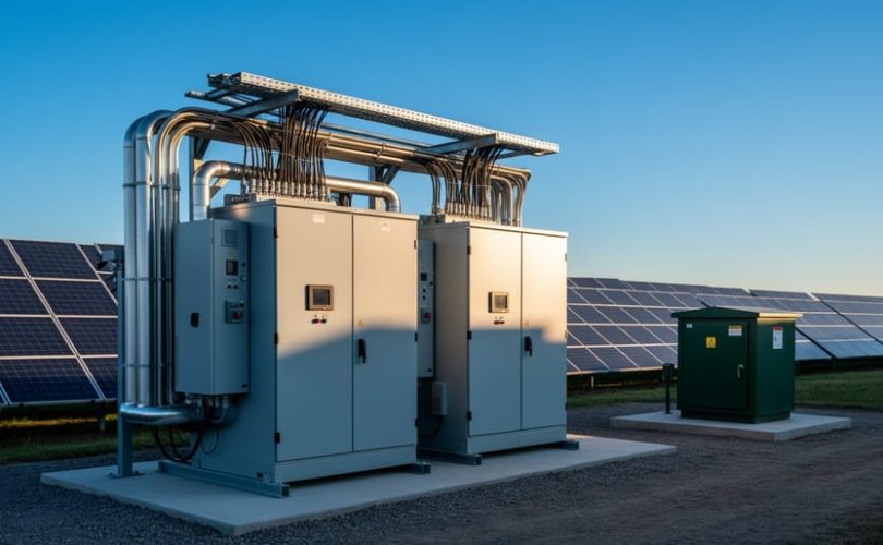
The AC collection system aggregates output from multiple inverters, often requiring voltage transformation to match utility requirements. Commercial and utility-scale installations typically step up voltage from 480V or 600V inverter output to medium-voltage distribution levels between 12.47kV and 34.5kV, reducing transmission losses over distance. This transformation occurs through pad-mounted or substation transformers specifically rated for solar applications.
Power quality remains a paramount consideration throughout the AC system. Harmonic distortion, voltage fluctuations, and reactive power must be managed to maintain grid stability and comply with IEEE 1547 interconnection standards. Proper conductor sizing accounts for continuous current capacity, voltage drop limitations, and temperature derating factors specific to installation conditions.
Protection coordination on the AC side requires careful selection and calibration of overcurrent devices, including circuit breakers, fuses, and relays. These components must selectively isolate faults while maintaining system operation elsewhere, protecting both personnel and equipment from electrical hazards during normal operation and fault conditions.
Key Components of an Inverter AC System
The AC-side of an inverter system comprises several critical components that ensure safe, efficient power delivery from the inverter to the grid or load center. Understanding these elements is essential for proper system design and code compliance.
Conductors form the backbone of AC distribution, sized according to continuous current ratings, voltage drop limitations, and National Electrical Code requirements. Proper wire sizing prevents overheating and efficiency losses while accommodating ambient temperature conditions and installation methods.
Transformers step up voltage levels for efficient power transmission, particularly in utility-scale installations. They provide isolation, voltage matching, and can facilitate grounding configurations required by utility interconnection agreements.
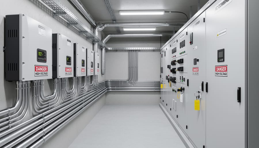
Switchgear and disconnects enable safe operation and maintenance by providing visible isolation points. These components must be rated for the maximum available fault current and include both manual and automatic switching capabilities.
Protection devices including circuit breakers, fuses, and ground fault protection equipment safeguard against overcurrent, short circuits, and ground faults. Proper coordination ensures selective operation, isolating faults at the nearest protective device without unnecessarily disrupting the entire system.
Metering equipment monitors power production, consumption, and bidirectional flow for net metering applications. Advanced meters provide real-time performance data essential for system optimization and revenue tracking in commercial installations.
Inverter Sizing: Matching Capacity to System Requirements
DC-to-AC Ratio and Its Impact on System Performance
Properly sizing the DC array relative to the inverter’s AC output capacity significantly influences both energy production and project economics. This relationship, known as the DC-to-AC ratio or inverter loading ratio, represents a fundamental design consideration in photovoltaic system optimization.
The DC-to-AC ratio expresses the installed DC capacity divided by the inverter’s rated AC output. While a 1:1 ratio might seem intuitive, most commercial and utility-scale installations employ ratios ranging from 1.1:1 to 1.35:1. This intentional oversizing strategy recognizes that solar arrays rarely operate at their nameplate capacity due to environmental factors including temperature, soiling, shading, and the sun’s angle of incidence throughout the day.
At ratios around 1.15:1, systems typically achieve optimal balance between maximizing energy harvest and minimizing clipping losses—periods when DC production exceeds inverter capacity and excess energy cannot be converted. Higher ratios, approaching 1.35:1, prove economically advantageous in regions with substantial diffuse irradiance or where DC component costs are significantly lower than inverter costs. These configurations accept modest clipping losses during peak production hours in exchange for substantially improved performance during the majority of operational hours when irradiance levels remain below optimal.
The financial implications extend beyond simple energy production. Higher DC-to-AC ratios reduce the cost per watt of AC capacity while enabling the inverter to operate closer to its peak efficiency point more frequently throughout the day. However, designers must carefully evaluate the trade-offs: excessive clipping reduces overall system performance ratio, while inverter warranty conditions may restrict maximum DC input levels. Site-specific factors including geographic location, tilt angle, orientation, and local incentive structures ultimately determine the optimal ratio for each installation.
Voltage Considerations for AC Output
Selecting the appropriate AC output voltage is a critical design decision that directly impacts system efficiency, equipment costs, and grid integration capabilities. For residential and small commercial installations typically under 100 kW, 208V or 240V three-phase systems are standard, matching common utility service voltages and minimizing transformation requirements. As system capacity increases to 500 kW and beyond, 480V becomes the preferred choice, offering reduced current levels and consequently smaller conductors, lower resistive losses, and more cost-effective switchgear.
Large-scale utility projects exceeding several megawatts often require medium voltage collection systems, typically ranging from 12.47 kV to 34.5 kV. This voltage step-up occurs at pad-mounted transformers or inverter-integrated solutions, enabling efficient power transmission across extended distances within the solar array while maintaining acceptable voltage drop limits below 3 percent. The selection process must account for utility interconnection requirements, which often dictate the point of common coupling voltage level.
Distance between inverter locations and the point of interconnection significantly influences voltage selection. Longer transmission distances favor higher voltages to minimize conductor sizing and I-squared-R losses. Consulting with the local utility early in the design phase ensures compliance with technical specifications and facilitates smoother interconnection approval processes.
Environmental and Operational Derating Factors
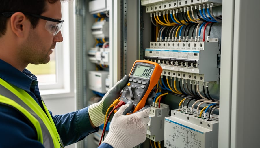
Environmental conditions and continuous operation requirements significantly impact inverter AC capacity, necessitating careful derating considerations during system design. Temperature represents the most critical environmental factor, as inverters typically experience reduced output capacity when ambient temperatures exceed manufacturer-specified thresholds, commonly around 25°C to 40°C. Most manufacturers provide derating curves showing capacity reductions of 1-3% per degree Celsius above baseline conditions. These thermal limitations stem from semiconductor component specifications and cooling system constraints.
Elevation also affects inverter performance due to reduced air density at higher altitudes, which diminishes cooling effectiveness. Inverters installed above 1,000 meters typically require additional derating, with manufacturers specifying capacity reductions of approximately 1% per 100 meters of elevation gain. This factor proves particularly relevant for mountain installations or high-plateau solar farms.
Continuous operation at maximum capacity accelerates component aging and increases failure risk. Industry best practices recommend sizing inverters with adequate margin, typically maintaining operation below 90-95% of rated capacity during peak conditions. This approach enhances system reliability, extends equipment lifespan, and provides headroom for temperature variations. Protection coordination schemes must account for these derated capacities to ensure proper circuit breaker sizing and overcurrent device selection, preventing nuisance tripping while maintaining safety compliance with electrical codes.
AC Collection System Design: From Inverter to Point of Interconnection
Collection System Topologies
AC collection systems in photovoltaic installations utilize three primary topologies, each offering distinct advantages for different project scales and site conditions.
Radial configurations represent the simplest and most cost-effective approach, particularly suited for small to medium-sized installations. In this design, individual inverter outputs connect sequentially along a single feeder cable that terminates at the main service equipment or point of interconnection. The radial topology minimizes conductor costs and simplifies installation, making it ideal for straightforward site layouts. However, this configuration offers no redundancy—a fault anywhere along the feeder affects all downstream inverters. Applications include residential systems, commercial rooftop arrays, and smaller ground-mount installations where reliability requirements permit single-path power collection.
Loop topologies provide enhanced reliability through redundant current paths. Inverters connect to a continuous loop of conductors, allowing power to reach the collection point via two routes. If a fault occurs at any location, the system maintains partial functionality by routing power through the alternate path. This configuration suits mission-critical applications where downtime costs justify the increased conductor and switchgear investment. Loop systems find application in large commercial facilities, utility-scale plants with strict availability requirements, and installations where maintenance access may be limited.
Hybrid designs combine radial and loop elements to optimize cost and reliability. Common implementations include multiple radial strings with loop interconnections or radial feeders with strategic tie points. These configurations allow designers to balance redundancy needs against budget constraints, targeting enhanced reliability for critical sections while maintaining cost efficiency elsewhere. Hybrid topologies frequently appear in medium to large commercial installations and community solar projects requiring flexible expansion capabilities.
Conductor Sizing and Voltage Drop Calculations
Proper AC conductor sizing balances electrical safety, system efficiency, and project economics. The National Electrical Code (NEC) Article 690 establishes minimum conductor ampacity requirements, mandating that AC conductors handle at least 125% of the inverter’s continuous output current. However, code compliance represents only the baseline—minimizing voltage drop ensures optimal energy harvest and inverter performance.
Voltage drop calculations follow Ohm’s Law principles, considering conductor resistance, current flow, and circuit length. Industry best practices recommend limiting AC voltage drop to 2% or less between the inverter and point of interconnection. Excessive voltage drop reduces system efficiency, increases conductor heating, and may cause inverter operational issues or premature disconnection.
The fundamental conductor sizing principles apply across both DC and AC systems, though AC calculations must account for power factor and three-phase configurations when applicable. Economic analysis weighs upfront conductor costs against long-term energy losses—larger conductors reduce resistive losses but increase material expenses.
Utilize NEC ampacity tables (Chapter 9, Table 9) alongside manufacturer specifications for accurate sizing. Online voltage drop calculators streamline complex calculations, though understanding underlying principles ensures proper verification and system optimization for varying installation conditions.
Transformer Selection and Placement
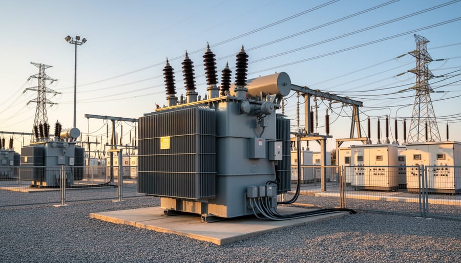
Selecting the appropriate step-up transformer requires careful consideration of both technical specifications and installation logistics. Pad-mount transformers offer ground-level accessibility for maintenance and are widely preferred in utility-scale installations, while overhead transformers may be cost-effective for smaller systems with existing pole infrastructure. Key selection criteria include voltage ratio matching your inverter output to grid requirements, appropriate kVA rating with consideration for harmonic loading, and impedance values that support proper protection coordination.
Transformer placement significantly impacts collection system efficiency and reliability. Position transformers to minimize AC cable runs from inverter stations, reducing voltage drop and conductor costs. Maintain adequate clearances per NEC Article 450 for safety and cooling requirements. In large arrays, strategically locating transformers creates logical collection zones that simplify protective device coordination. Consider environmental factors including flood zones, accessibility for maintenance vehicles, and thermal management in hot climates. Proper placement also facilitates future expansion while maintaining balanced loading across collection feeders, optimizing overall system performance and reducing losses throughout the AC collection network.
Protection Coordination: Safeguarding Your AC System
Overcurrent Protection Principles
Protecting inverter AC systems from overcurrent conditions requires implementing appropriate protective devices that respond rapidly to fault conditions while remaining stable during normal operation. Three primary protection devices serve distinct roles in photovoltaic installations: circuit breakers, fuses, and reclosers.
Circuit breakers provide reusable overcurrent protection with adjustable trip characteristics. They interrupt current flow when exceeding predetermined thresholds, protecting conductors and equipment from thermal and magnetic stress. Modern electronic circuit breakers offer precise coordination capabilities essential for selective protection in multi-inverter installations.
Fuses deliver reliable, cost-effective protection through sacrificial elements that melt under excessive current. While requiring replacement after operation, fuses excel in interrupting extremely high fault currents and provide inherent current-limiting properties. Current-limiting fuses are particularly valuable in protecting inverter output circuits where semiconductor components demand fast-acting protection.
Reclosers automatically restore power after temporary faults, reducing outage duration in utility-interactive systems. Though less common in smaller installations, reclosers prove valuable in large-scale solar farms with extensive AC collection networks.
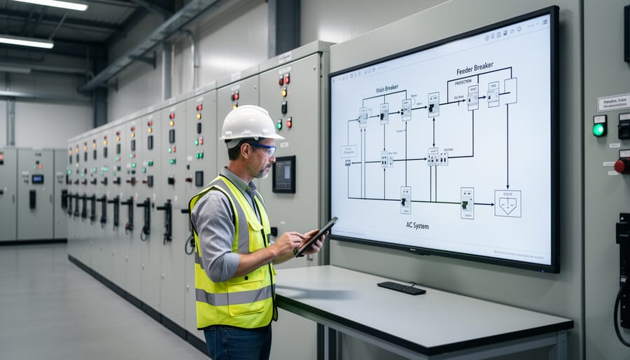
Proper device selection demands accurate fault current calculations accounting for utility contribution, inverter fault current contribution (typically 1.1 to 1.2 times rated current), and conductor impedance. Protection devices must coordinate properly, ensuring downstream devices operate before upstream devices during fault conditions, thereby minimizing affected system portions while maintaining continuous operation of healthy circuits.
Arc Flash Hazards and Mitigation
Arc flash hazards represent a critical safety concern on the AC side of inverter systems, where high available fault currents can create explosive energy releases capable of causing severe injuries or fatalities. The AC collection system, with its concentrated power flows and multiple parallel sources, often presents higher arc flash risk than traditional electrical installations. Conducting comprehensive arc flash hazard analysis studies is essential for every solar installation, calculating incident energy levels at each potential point of work based on system configuration, available fault current, protective device characteristics, and clearing times.
These studies inform proper labeling requirements mandated by NFPA 70E and NEC Article 110.16, which require arc flash warning labels at service equipment, switchboards, panelboards, and motor control centers. Labels must display the nominal system voltage, arc flash boundary distance, incident energy level, and required personal protective equipment (PPE) category. Design strategies to reduce hazard levels include limiting fault current through impedance, implementing faster-acting protective devices, using current-limiting fuses, installing arc-resistant switchgear, and designing systems with reduced working distances. Zone-selective interlocking between protective devices minimizes clearing times, while proper maintenance intervals ensure protection coordination remains effective. Educational programs emphasizing arc flash awareness and proper work practices are fundamental to maintaining worker safety in solar installations.
Ground Fault Protection and System Grounding
Proper grounding and ground fault protection are fundamental safety requirements for inverter AC systems, protecting both personnel and equipment from electrical hazards. Solar installations typically employ solidly grounded systems, where the neutral conductor connects directly to earth, providing a low-impedance path for fault currents. This configuration enables overcurrent protection devices to quickly detect and clear ground faults. In larger commercial installations, resistance grounded systems may be utilized to limit ground fault current magnitude while still allowing detection, though this approach is less common in standard photovoltaic applications.
Ground fault detection methods include residual current devices and ground fault protection relays integrated within modern inverters. These systems continuously monitor current balance between phase and neutral conductors, detecting even small leakage currents that indicate insulation breakdown or unintended current paths. NEC Article 690 mandates specific ground fault protection requirements for PV systems, including automatic disconnection when faults exceed predetermined thresholds. Equipment grounding conductors must be properly sized according to overcurrent device ratings, ensuring fault currents safely return to the source without creating dangerous voltage potentials on exposed conductive surfaces.
Coordination Time-Current Curves
Developing effective time-current curves requires systematic analysis of all protective devices in the AC system path, from inverter output through combiner panels to the utility interconnection point. Begin by plotting the inverter’s overcurrent protection characteristics, typically provided by manufacturers as let-through curves showing response times at various fault current magnitudes. Layer upstream devices sequentially, ensuring each curve sits above and to the left of downstream devices with adequate separation margins—typically 0.2 to 0.4 seconds at all current levels to achieve selective coordination.
Consider the asymmetrical nature of inverter fault contributions, which differ significantly from traditional rotating machine sources. Modern inverters limit fault current to approximately 1.1 to 1.5 times rated output, affecting coordination intervals. Account for device tolerances and temperature variations when establishing minimum separation between curves. Verify coordination at minimum and maximum fault current scenarios, particularly at the point of common coupling where utility and solar sources combine. Document assumptions clearly, including cable impedances, transformer characteristics, and ambient conditions. Software tools facilitate this analysis, but manual verification of critical coordination points remains essential for reliable protection schemes that prevent nuisance tripping while ensuring rapid fault isolation.
Code Compliance and Utility Interconnection Requirements
National Electrical Code (NEC) Article 690 and 705
The National Electrical Code provides essential safety standards for photovoltaic AC systems through Article 690 (Solar Photovoltaic Systems) and Article 705 (Interconnected Electric Power Production Sources). These regulations ensure proper installation, protection, and operation of inverter-based solar systems.
Article 690 mandates that all PV systems include readily accessible disconnection means to isolate the inverter from both DC and AC sources during maintenance or emergencies. Ground-fault protection is required for array circuits operating above 50 volts, while equipment grounding conductors must be sized according to NEC Table 250.122. The code also specifies maximum voltage and current ratings for all system components, ensuring compatibility and safety margins.
Article 705 addresses the interconnection of utility-interactive inverters with the electrical grid. Key requirements include dedicated overcurrent protection devices sized at 125 percent of the inverter’s continuous output current rating. The busbar or conductor supplying multiple inverters must comply with the 120 percent rule, limiting the sum of all overcurrent devices to 120 percent of the busbar rating. Additionally, permanent warning labels identifying all power sources must be installed at service equipment locations.
Proper grounding systems are critical, requiring bonding of all metallic equipment enclosures and establishing an effective ground-fault current path. These NEC provisions form the regulatory foundation for designing compliant, safe photovoltaic AC systems.
IEEE 1547 and Utility Interconnection Standards
IEEE 1547 establishes the technical specifications for interconnecting distributed energy resources, including photovoltaic systems, to the electric utility grid. This standard mandates critical safety and power quality requirements that inverter AC systems must satisfy to receive interconnection approval. Understanding these requirements is essential for properly designing protection schemes and ensuring compliant installations.
The standard addresses voltage and frequency ride-through capabilities, requiring inverters to remain connected during minor grid disturbances while disconnecting during serious faults. Trip settings specify precise voltage and frequency boundaries with corresponding clearing times. For example, inverters must cease energizing the utility within specified timeframes when voltage exceeds 110 percent or drops below 88 percent of nominal values.
Anti-islanding protection represents a critical IEEE 1547 requirement, preventing inverters from continuing to energize isolated portions of the utility grid during outages. This protection safeguards utility workers and maintains system stability. Modern inverters incorporate multiple detection methods, including active frequency drift and voltage shift techniques, to identify islanding conditions within the mandated two-second detection window.
Recent amendments to IEEE 1547 have introduced advanced grid-support functions, enabling inverters to provide voltage regulation through reactive power control and contribute to grid stability during disturbances. These enhanced capabilities position solar installations as active grid participants rather than passive generators, fundamentally transforming their role in modern electrical infrastructure.
Common Design Mistakes and How to Avoid Them
Even experienced professionals encounter design challenges when configuring inverter AC systems for photovoltaic installations. Understanding these common pitfalls and their solutions is essential for creating reliable, code-compliant systems.
One of the most prevalent mistakes involves undersized conductors. Many designers calculate wire gauge based solely on continuous current ratings without adequately accounting for voltage drop, especially on longer runs between inverters and the point of interconnection. This oversight leads to efficiency losses and potential code violations. The solution requires calculating both ampacity and voltage drop simultaneously, typically limiting voltage drop to 2-3% under full load conditions. Applying proper conductor sizing principles from the outset prevents costly redesigns and ensures optimal system performance.
Inadequate protection coordination represents another critical design error. Some installations feature overcurrent protection devices that fail to coordinate properly, meaning upstream breakers trip before downstream devices during fault conditions. This cascades into unnecessary system-wide shutdowns rather than isolated circuit protection. Designers should develop time-current coordination studies, ensuring selective coordination throughout the protection hierarchy. This involves selecting circuit breakers and fuses with appropriate interrupt ratings and time-delay characteristics.
Temperature derating factors are frequently overlooked, particularly in outdoor combiner boxes and equipment exposed to direct sunlight. Ambient temperatures can significantly exceed standard rating conditions, reducing conductor ampacity and device performance. Always apply appropriate temperature correction factors based on actual installation conditions and local climate data.
Finally, inadequate documentation and labeling creates operational hazards and compliance issues. Complete as-built drawings, protection device settings, and clear labeling of all disconnect points are essential for safe maintenance and troubleshooting throughout the system’s operational life.
The effective operation of inverter AC systems in solar PV installations depends fundamentally on the integrated optimization of three critical elements: proper inverter sizing, robust AC collection network design, and comprehensive protection coordination. These components function not as isolated technical considerations but as interconnected subsystems that collectively determine installation safety, operational efficiency, and long-term performance. Understanding this interdependence is essential for successful project implementation.
Proper inverter sizing establishes the foundation, determining voltage levels, current capacities, and power flow characteristics that cascade through the entire AC-side infrastructure. The AC collection system must then accommodate these parameters while minimizing losses and maintaining voltage stability across all operating conditions. Protection coordination completes this technical framework by ensuring that any system disturbance is detected and isolated swiftly, safeguarding both equipment and personnel.
Achieving excellence in inverter AC system design requires commitment to holistic system design principles. Professionals must evaluate trade-offs, apply code requirements rigorously, and verify designs through detailed analysis. Mose Solar supports this mission through collaborative educational initiatives with universities and comprehensive training programs, empowering the next generation of renewable energy professionals to design systems that meet the highest standards of safety, efficiency, and regulatory compliance.