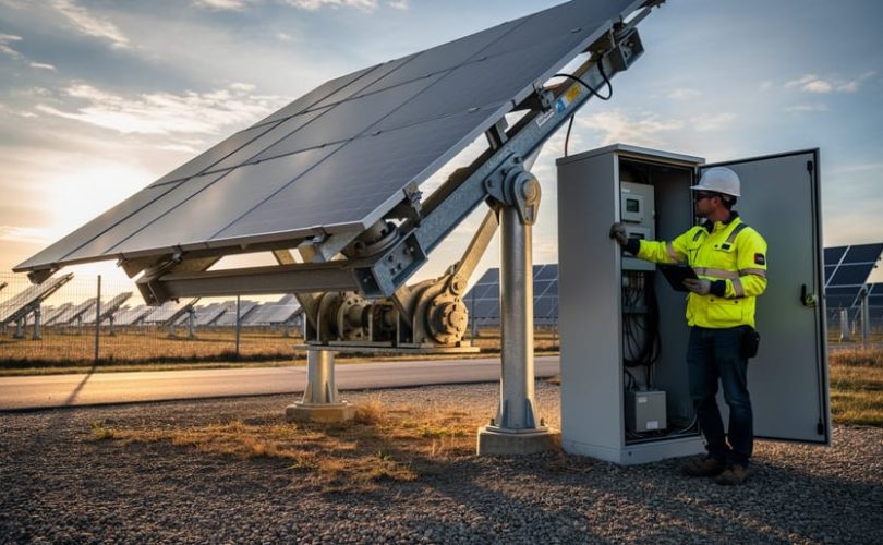
The most common reason PV tracker systems fail to follow the sun is a corrupted position sensor or a communication fault between the controller and drive motor. Before calling for professional service, check whether the tracker responds to manual override commands from the control interface. If the panel moves on command but won’t auto-track, the problem lies in sensor calibration or software settings. If it doesn’t respond at all, inspect circuit breakers, communication cables, and power supply continuity.
Tracker malfunctions directly impact energy production. When panels remain misaligned to the sun’s path throughout the day, generation losses accumulate quickly. For operations and maintenance technicians, rapid diagnosis separates minor recalibration from component replacement or motor failure.
This guide walks through systematic troubleshooting of single-axis and dual-axis tracker systems, from identifying symptoms at the inverter or monitoring dashboard through step-by-step diagnostic procedures. You’ll learn how to distinguish between sensor drift, mechanical binding, controller programming errors, and drive system failures. Each section provides field-tested repair protocols used by O&M teams managing utility-scale and commercial installations.
Safety is paramount. Tracker systems combine high-voltage DC power, moving mechanical parts, and remote control electronics. Always verify lockout-tagout procedures before touching any component, confirm panels are isolated from electrical circuits, and understand when professional intervention is required. Replacing a drive motor or reprogramming a PLC controller demands specialized training and equipment.
For facility managers and installers seeking to reduce service calls and extend equipment life, the final sections cover preventive maintenance schedules, environmental factors that accelerate component degradation, and documentation practices that streamline future repairs. Our educational programs, developed in collaboration with leading universities, prepare photovoltaic professionals to maintain these sophisticated systems with confidence and precision.
Identifying Tracker Malfunction Symptoms
Detecting tracker problems early can mean the difference between a quick adjustment and a costly system failure. Visual inspection remains your first line of defence. Walk the array during midday when the sun’s position is obvious, panels should directly face the solar disc, not off at an angle. If you notice entire rows frozen in position while neighbouring trackers move normally, or panels that gradually drift away from optimal orientation throughout the day, something has failed in the control or drive chain.
Movement irregularities often signal specific component issues. Jerky, stuttering motion typically points to motor or gearbox problems, while trackers that move part-way then stop suggest actuator faults or mechanical binding. Panels stuck in a flat, horizontal position during normal operating hours have likely entered protective stow mode, either through a valid high-wind condition or a false sensor trigger that needs investigation.
Your monitoring system provides crucial diagnostic data beyond what eyes can see. Modern solar monitoring alerts flag performance deviations that reveal tracking failures before they become obvious in the field. Watch for these indicators:
- Power output noticeably lower than neighbouring identical tracker rows under the same conditions
- Morning and evening generation curves that flatten prematurely compared to historical patterns
- Inverter data showing reduced DC input from specific tracker sections
- Position sensor readings that no longer match expected sun azimuth and elevation angles
- Communication loss alerts from tracker controllers that stop reporting status
Performance anomalies matter even when they seem minor. A tracker that consistently underperforms by just a few percentage points indicates early-stage sensor drift or partial mechanical failure that will worsen without intervention. Check whether multiple trackers show the same symptoms simultaneously, which suggests a system-wide control issue rather than isolated component failure. The clearer your symptom picture before you start repairs, the faster you reach the root cause.
Common Causes of PV Tracker Failure
Sensor and Control System Issues
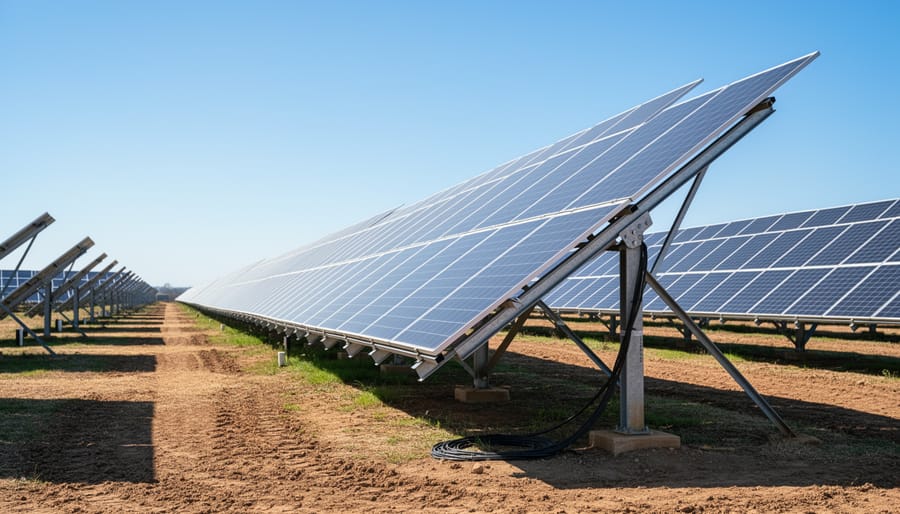
Position sensors and control units serve as the brains of tracking systems, determining where panels should point throughout the day. When these components fail, arrays can freeze in place, drift off target, or oscillate between incorrect positions, all of which reduce energy capture.
Position sensor failures represent the most common control issue. These sensors measure the tracker’s current angle and report it to the controller. Over time, sensor drift occurs as calibration shifts due to temperature cycling, vibration, or moisture intrusion. A sensor reporting an incorrect angle causes the controller to position the array wrongly, believing it’s already at the target orientation when it isn’t. Physical damage from wildlife, severe weather, or installation errors can also knock sensors out of alignment or break their mounting brackets.
Control unit problems typically stem from corrupted firmware, failed memory chips, or power supply issues within the controller itself. Firmware corruption can cause erratic behavior, the controller may send conflicting commands, fail to update position calculations, or ignore sensor inputs entirely. Power supply failures within the control box prevent proper operation even when field power reaches the unit.
Sun position algorithm errors occur less frequently but prove difficult to diagnose. These calculation failures happen when geographic coordinates are entered incorrectly during commissioning, time-zone settings drift after daylight saving transitions, or the algorithm fails to account for local magnetic declination. The tracker moves smoothly but systematically points away from optimal angles throughout the day.
Communication breakdowns between sensors and controllers produce intermittent failures that worsen during temperature extremes or high electromagnetic interference periods. Corroded connection terminals and damaged signal cables account for most communication issues in aging installations.
Mechanical and Drive System Problems
Mechanical failures represent the most visible category of tracker problems, panels that won’t move, grinding noises during rotation, or erratic positioning despite functioning sensors. Unlike control system glitches, these issues stem from physical wear or damage to components that bear the weight and wind loads of large panel arrays through thousands of tracking cycles per year.
Motor Failures
Drive motors propel tracker rotation, and they fail when bearings seize, windings overheat, or brushes wear out in brushed designs. A motor that hums without turning typically indicates a locked rotor from mechanical binding or a seized bearing. Complete electrical silence suggests wiring failure or internal winding damage. Test motor function by disconnecting it from the drive train and running it independently; if it operates freely, the problem lies downstream in the gearbox or actuator.
Gearbox Wear and Lubrication
Gearboxes reduce motor speed to the slow rotation rates trackers require. Insufficient lubrication causes accelerated gear tooth wear, producing metal particles that contaminate the oil and create grinding sounds during movement. Inspect lubricant level and condition during routine maintenance; dark, gritty oil or oil below the fill line requires immediate attention. Damaged gears produce erratic movement or slippage, the motor runs but tracking position doesn’t change proportionally.
Actuator Malfunctions
Linear actuators in some single-axis designs extend and retract to adjust panel tilt. Internal seal failures allow moisture into the actuator body, corroding the rod and damaging internal components. A bent actuator rod from wind damage or debris impact prevents smooth extension. Check for hydraulic fluid leaks in hydraulic actuators or excessive play in ball screw actuators. Replace rather than repair failed actuators; the precision required makes field rebuilds unreliable.
Mechanical Obstructions
Vegetation growth, accumulated snow or ice, debris lodged in the drive mechanism, or structural damage from extreme weather physically block tracker movement. Visual inspection identifies most obstructions. After clearing, manually rotate the tracker through its full range to verify free movement before re-energizing the drive system. Check mounting bolts and structural connections for loosening that allows unwanted play in the system.
Power and Communication Failures
Electrical supply interruptions and communication network failures can halt tracker operation entirely, even when mechanical components remain functional. A disrupted power supply, whether from a tripped breaker, damaged supply cable, or voltage sag, leaves motors and controllers without the energy needed to adjust panel position. When power supply fails intermittently, trackers may freeze in their last commanded position or default to a safe stow angle, resulting in substantial energy production losses during peak sun hours.
Wiring damage presents a particularly insidious problem. Rodent activity, UV degradation of cable insulation, and physical abrasion from moving tracker parts can create intermittent faults that appear only under certain operating conditions. Corroded connections at junction boxes or terminal blocks introduce resistance that disrupts voltage levels, causing erratic behavior. These electrical faults often manifest as random movement errors rather than complete system failure, complicating diagnosis.
Communication network breaks between central controllers and individual tracker rows disable coordinated tracking. Modern tracker arrays rely on network protocols, typically RS-485, Modbus, or proprietary systems, to synchronize movement across multiple units. A single damaged network cable or failed repeater can orphan entire rows of trackers, leaving them stationary while adjacent sections continue to track the sun. Network diagnostics must verify signal integrity, protocol handshaking, and data packet transmission to restore coordinated operation.
Environmental and Weather-Related Causes
Environmental conditions pose significant challenges to tracker reliability. High winds trigger protective stow modes that park arrays at safe angles, preventing structural damage but temporarily halting tracking. If anemometers malfunction or communication fails, trackers may not stow when needed or may remain stowed unnecessarily, reducing generation.
Ice and snow accumulation prevent mechanical movement and add weight that strains drive components. Freezing temperatures can damage seals and cause lubricants to thicken, reducing motor efficiency. Debris such as vegetation, dust buildup, or bird nesting interferes with sensors and obstructs movement paths.
Corrosion from salt air, humidity, or industrial pollutants degrades electrical connections and mechanical joints over time. Exposed wiring terminals oxidize, increasing resistance and causing intermittent failures. Regular environmental inspections identify these issues before they escalate into complete system failures, particularly in coastal or industrial installations where corrosive exposure accelerates component degradation.
Step-by-Step Troubleshooting and Repair Process
Initial Safety and Visual Assessment
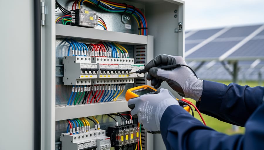
Before investigating any tracker malfunction, secure the work area to protect personnel and equipment. Apply lockout/tagout for hazardous energy by disconnecting power to the affected tracker row, tagging control panels and breakers, and verifying zero-energy state with a multimeter. Notify site operations that maintenance is in progress, and establish a restricted zone around moving tracker components.
Once secured, conduct a visual inspection before any hands-on work. Walk the tracker row and note obvious abnormalities: panels misaligned with adjacent rows, actuators fully extended or retracted, visible damage to torque tubes or bearings, loose wiring at junction boxes, or debris blocking movement. Check for error codes or alerts in the monitoring system, which often identifies which tracker in a string has stopped reporting. This preliminary assessment, following the same principles used in expert troubleshooting for other PV issues, establishes a baseline before deeper diagnostics and prevents wasting time on secondary symptoms rather than root causes.
Testing Control Systems and Sensors
Start by isolating the tracker’s controller from the rest of the system. Most trackers have a local control panel or display that shows current status and allows manual commands. Put the controller into manual mode and command a small movement, if the tracker responds and holds position when commanded, the controller can receive instructions and execute them. If manual commands work but automatic tracking doesn’t, your problem sits with sensors or algorithms rather than the controller hardware itself.
Check sensor readings next. Position sensors report where the tracker thinks it is, while solar sensors or inclinometers tell the controller where it needs to be. Compare the controller’s displayed angle to the tracker’s actual physical position measured with an inclinometer or laser level. A discrepancy means sensor drift or mounting issues; even minor sensor errors compound into noticeable tracking inaccuracy that cuts energy production. Recalibrate or replace sensors showing persistent offsets.
Validate sun position calculations by comparing the tracker’s target angle to calculated solar elevation and azimuth for your site coordinates and current time. Many controllers log target versus actual position; reviewing these logs reveals whether the algorithm sends correct commands. Incorrect site coordinates, wrong time zone settings, or outdated firmware can all cause systematic tracking errors where the tracker consistently leads or lags the sun’s movement.
Test communication between the controller and the site monitoring system by checking data flow in both directions. Verify that position data appears in your monitoring dashboard and that remote commands reach the tracker. Network issues often cause trackers to operate in isolation, continuing to track but failing to respond to stow commands or weather signals. Check physical connections, network configuration, and protocol settings to restore full communication.
Inspecting and Repairing Mechanical Components
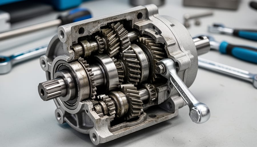
Once electronic causes are ruled out, turn your attention to the mechanical systems that physically move the tracker. Start with the drive motors. Disconnect power and manually rotate the tracker structure through its range of motion, it should move smoothly without jerky resistance or dead spots. If the structure binds or moves unevenly, you’ve likely found wear in the motor bearings or gearbox. Reconnect power and listen for unusual noises during operation: grinding, clicking, or high-pitched whining indicates internal damage requiring immediate attention.
Gearbox inspection demands both visual and tactile assessment. Remove the inspection cover and check lubricant level and condition. Fresh grease should appear clean and uniform; dark, gritty, or separated lubricant signals contamination or breakdown. Examine the gear teeth under adequate lighting for pitting, scoring, or excessive wear patterns. If you spot metal shavings in the lubricant, the gearbox needs replacement before catastrophic failure occurs.
For linear actuators, extend and retract them fully while watching for smooth, consistent movement. Measure stroke length against manufacturer specifications, shortened travel indicates internal wear. Check mounting points for loose bolts or elongated holes that allow play. Inspect rod seals for leaks; hydraulic fluid around the actuator body means seal failure and contamination risk.
Clear any debris lodged in the tracker frame, torque tube, or drive mechanisms. Vegetation growth, blown trash, or accumulated dirt can block movement or create uneven loading. After clearing obstructions, verify that all mechanical stops and limit switches are properly positioned and undamaged.
Electrical System Diagnostics
Electrical faults account for a significant portion of tracker failures, from complete loss of power to intermittent communication dropouts. Start by confirming that the main circuit breaker or disconnect supplying the tracker array remains closed and that upstream power sources are functioning. Use a multimeter to measure voltage at the tracker controller input terminals; compare readings against nameplate specifications to identify undervoltage conditions that prevent normal operation.
Inspect all visible wiring for physical damage, including chafing where cables pass through conduit fittings, rodent damage to insulation, and corrosion at connection points exposed to moisture. Pay particular attention to underground conduit transitions where water infiltration often causes shorts. Check wire nuts and terminal blocks for tightness, as vibration from tracker movement gradually loosens connections over time.
Test fuses and circuit protection devices using continuity measurements when power is isolated. Many tracker systems use blade-type automotive fuses in control boxes; these fail from overcurrent events or simply age-related fatigue. Replace any suspect fuses even if they test good, as marginal failures cause erratic behavior.
Measure voltage at each stage of the power distribution path: controller output to motor driver, driver output to actuator terminals, and sensor power supply rails. Voltage drops exceeding manufacturer tolerances point to resistance problems in wiring or failing components. Document all readings to track degradation trends across maintenance cycles.
Firmware Updates and Calibration
After completing mechanical or electrical repairs, firmware updates and calibration restore accurate tracking behavior. Firmware updates address software bugs, improve tracking algorithms, and add compatibility with new hardware revisions. Most tracker manufacturers release updates annually or when critical issues emerge. Check the manufacturer’s support portal for your tracker model’s latest firmware version and release notes detailing fixes or performance improvements.
Before updating firmware, document current system settings and create backups if the control interface allows. Follow the manufacturer’s installation procedure precisely, firmware updates typically upload through a direct connection to the controller or via the monitoring network. Never interrupt power during the update process, as incomplete installations can render controllers inoperable.
Calibration aligns the tracker’s position sensors with its physical orientation. Perform calibration after replacing sensors, actuators, or structural components, and whenever tracking accuracy visibly degrades. The calibration procedure varies by system but generally involves positioning the tracker at known reference angles, often true north or true south at solar noon, then instructing the controller to record those positions as baseline references. Some systems use built-in inclinometers; others require manual angle measurements with digital levels.
Reset tracking algorithms when sensors drift or after firmware updates change calculation methods. This process clears stored position data and re-establishes the tracker’s understanding of its orientation relative to the sun’s path. Most controllers offer a calibration wizard or reset function in their service menu. Verify calibration success by observing tracker movement through a full daily cycle and comparing panel orientation to the sun’s actual position at multiple times.
Preventive Maintenance Strategies to Avoid Tracker Failures
Systematic preventive maintenance reduces tracker failures and preserves performance over the system’s operational life. Unlike reactive repairs that address problems after downtime has already occurred, scheduled interventions catch degradation early and keep tracking accuracy within design tolerances.
The foundation of effective tracker maintenance combines routine inspections with condition monitoring. Visual walkthroughs identify obvious issues like loose fasteners, cable damage, or debris accumulation before they cause failures. Torque checks on structural connections prevent wind-induced loosening. Lubrication schedules for gearboxes and bearings follow manufacturer specifications, typically quarterly for high-movement components and semi-annually for less-stressed elements. Sensor calibration verification ensures tracking commands match actual solar position; even small alignment drift compounds energy losses across the array.
| Maintenance Task | Frequency | Responsible Party |
|---|---|---|
| Visual inspection and cleaning | Monthly | O&M technician |
| Lubrication of drive components | Quarterly | Mechanical specialist |
| Sensor calibration verification | Bi-annually | Controls technician |
| Electrical connection inspection | Annually | Electrical technician |
| Comprehensive system audit | Annually | Engineering team |
Implementing predictive maintenance strategies extends component life further. Vibration analysis on motors and gearboxes detects bearing wear before failure. Thermal imaging reveals electrical hot spots from loose connections or failing components. Production monitoring flags tracking errors when actual output falls below modeled expectations for current irradiance conditions. These techniques shift maintenance from time-based to condition-based, concentrating resources where degradation is actually occurring.
Documentation practices matter as much as the physical work. Maintenance logs track completed tasks, component replacements, and observed conditions over time. Trend analysis reveals patterns, like whether certain tracker rows experience faster wear due to local wind patterns or drainage issues. This data informs future maintenance schedules and helps justify component upgrades or design modifications.
Professional training ensures maintenance teams apply these maintenance tips correctly and safely. Mose Solar collaborates with universities to develop educational programs that prepare aspiring photovoltaic professionals for the specific demands of tracker system maintenance, combining classroom instruction with hands-on diagnostic practice. Skilled technicians recognize subtle indicators of impending failure and perform interventions with minimal system disruption, directly protecting long-term energy production.
Understanding PV Tracker System Components
PV tracker systems coordinate multiple subsystems to maintain optimal panel orientation throughout the day. Understanding how these components work together helps maintenance professionals diagnose failures efficiently and identify which elements require attention during troubleshooting.
The sensing subsystem forms the foundation of tracker operation. Sun position sensors, which may be photocells, pyranometers, or astronomical algorithms integrated into the control unit, detect the sun’s location. Position feedback sensors on the tracker itself, typically encoders, potentiometers, or limit switches, report the current panel angle back to the controller. These sensors must provide accurate data; even small errors compound over time, degrading tracking performance.
The control subsystem processes sensor data and makes positioning decisions. Modern controllers run firmware that calculates optimal panel angles based on geographic coordinates, time, and date, or responds directly to sensor readings comparing east-west light intensity. The controller sends command signals to drive components, adjusting tracking speed and direction. Communication interfaces allow remote monitoring and integration with plant-wide SCADA systems, enabling operators to detect anomalies before they cause significant energy losses.
Drive and actuation components convert control signals into physical movement. Single-axis trackers commonly use linear actuators or slew drives powered by DC or AC motors. Dual-axis systems add a second motor for tilt adjustment. Gearboxes reduce motor speed while increasing torque, allowing precise, controlled movement of heavy panel arrays. Bearings, structural pivots, and mounting hardware support the mechanical load while permitting rotation.
The structural frame ties everything together, providing rigid support for panels while allowing controlled movement. Torque tubes connect rows of panels into a unified tracking assembly, distributing wind loads and ensuring synchronized rotation. For professionals enrolled in PV training programs, working through the interaction of these subsystems, from sensor input through controller logic to motor actuation, builds the diagnostic logic needed for effective tracker maintenance and repair.
Frequently Asked Questions About PV Tracker Troubleshooting
Maintenance professionals and installers working with tracker systems often face similar challenges and decision points. These questions reflect the most common concerns encountered during diagnostic and repair work.
How do I know when a tracker problem requires a specialist rather than in-house maintenance?
Call a specialist when you encounter controller failures requiring firmware diagnosis, persistent mechanical issues after basic repairs, or problems involving tracker-specific proprietary components that void warranties if serviced incorrectly. Simple fixes like clearing obstructions, replacing worn bearings, or resetting stow modes typically fall within general maintenance capabilities.
What diagnostic tools are essential for tracker troubleshooting?
A basic kit includes a multimeter for electrical testing, infrared thermography equipment to detect overheating components, inclinometers or digital levels to verify positioning accuracy, and access to the tracker’s monitoring software for historical performance data. Many manufacturers also provide dedicated diagnostic interfaces for their control systems.
Can a tracker system continue partial operation while one unit is under repair?
Most installations allow individual tracker rows or zones to be isolated without shutting down the entire array. Modern systems include bypass functions that maintain power generation from functional units while repairs proceed, though overall site output will be reduced proportionally to the offline capacity.
How much does misalignment reduce energy production?
The impact varies with the degree of misalignment and time of day. Small deviations may cause modest efficiency losses, while complete tracking failure that leaves panels fixed can significantly reduce capture compared to proper tracking performance, particularly during morning and evening hours when sun angles change most rapidly.
Another frequent concern involves response time expectations. Mechanical failures like motor or actuator problems often receive same-day attention because they cause immediate production losses and are relatively straightforward to diagnose. Control system bugs or intermittent sensor drift may require extended monitoring periods to identify patterns before effective repairs can be implemented.
Operators commonly ask whether weather-related stow events indicate problems. High wind stow is a protective feature, not a malfunction. Trackers should return to normal operation once wind speeds drop below threshold levels, typically within minutes to hours depending on conditions. If trackers remain in stow position after weather clears, investigate control system inputs and manual override settings.
The question of repair versus replacement arises particularly with aging tracker installations. Components like motors, actuators, and sensors have defined service lives and become candidates for replacement rather than repeated repairs when failure frequency increases. Structural elements like torque tubes and foundations, however, often outlast multiple generations of mechanical and electronic components with proper maintenance.
Professionals transitioning into tracker maintenance often ask about training requirements. While basic mechanical and electrical skills provide a foundation, tracker-specific knowledge significantly improves diagnostic speed and repair quality. Formal training programs developed through collaborations between industry partners and universities prepare technicians for the specialized demands of modern tracking systems, covering both theory and hands-on troubleshooting approaches.
Systematic tracker diagnostics protect the investment solar installations represent. The troubleshooting framework outlined here, starting with symptom identification, progressing through methodical testing of control and mechanical systems, and concluding with calibration, reduces guesswork and downtime. When technicians follow this structured approach, they isolate root causes faster and avoid replacing components unnecessarily.
Preventive maintenance delivers greater returns than reactive repairs. Regular inspections catch sensor drift, lubrication needs, and wiring degradation before they cascade into full system failures. Documented maintenance schedules, combined with staff training in diagnostic procedures, keep tracker arrays performing at design capacity year after year.
The renewable energy sector needs skilled professionals who understand both troubleshooting protocols and the engineering principles behind tracker operation. Structured education builds this competency. Mose Solar collaborates with universities to develop training programs that prepare aspiring photovoltaic professionals for real-world challenges, from field diagnostics to preventive maintenance planning. Investing in professional development strengthens the workforce supporting solar energy expansion and ensures tracker systems continue maximizing generation potential.