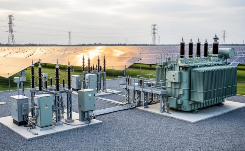
Electric substation design for utility-scale photovoltaic projects requires a systematic approach to medium-voltage engineering, equipment selection, and grid interconnection planning that typically spans 6-12 months from concept to final utility approval. The process centers on transforming DC solar generation into synchronized AC power at distribution or transmission voltage, coordinating protection schemes with utility requirements, and ensuring equipment ratings match both normal operation and fault conditions.
Grid-connected solar projects depend on properly engineered substations to deliver power safely and reliably. Unlike residential installations, utility PV substations handle megawatt-scale power flows, manage complex protection coordination with existing utility infrastructure, and must satisfy stringent interconnection standards that vary by region and utility provider. The design phase determines equipment cost, construction timeline, and operational performance for the project’s 25-year lifespan.
Success in substation engineering demands collaboration between solar developers, utility engineers, and consulting firms specializing in power systems. The interconnection study process, conducted by the serving utility, establishes voltage requirements, fault duty ratings, protection schemes, and equipment specifications that form the foundation of your design. Most projects require a step-up transformer (typically 34.5 kV or higher), switchgear rated for utility fault currents, protective relaying that coordinates with grid devices, and metering equipment meeting revenue-grade accuracy standards.
This methodology walks through the complete design workflow: from interpreting interconnection study results and selecting major equipment to developing single-line diagrams, coordinating protection settings, and preparing construction documents for utility review. Whether you’re an aspiring substation engineer, a solar project developer building technical capacity, or a student pursuing renewable energy expertise, this structured approach provides the technical foundation needed to execute medium-voltage substation projects. Mose Solar collaborates with university programs to advance substation engineering education and offers specialized training for professionals entering the utility solar sector.
Understanding MV Substation and Interconnection Fundamentals for Utility PV
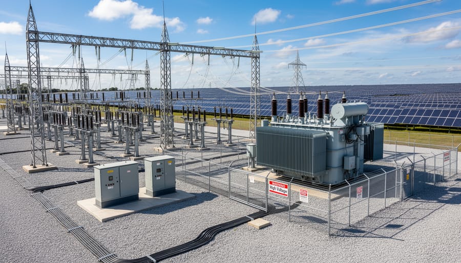
Medium-voltage substations serve as the critical interface between utility-scale photovoltaic arrays and the electrical transmission grid, performing four core functions that enable reliable power delivery. First, they collect distributed DC power from multiple inverter stations across the solar field, already converted to AC at voltages typically between 480V and 690V. Second, they step up this medium voltage to transmission levels, often 34.5kV, 69kV, or 138kV depending on utility requirements, using power transformers sized to handle the full generating capacity of the installation. Third, they provide protection and switching capabilities that isolate faults, coordinate with grid protection schemes, and allow safe disconnection for maintenance. Fourth, they facilitate grid interconnection by housing metering equipment, revenue-grade instrumentation, and control systems that satisfy utility technical and commercial requirements.
Understanding the terminology clarifies design decisions. Medium voltage generally refers to distribution-class voltages from 1kV to 69kV, the range most utility PV substations operate within. Step-up transformers increase voltage from the inverter output level to the point of interconnection voltage, with ratings matching project capacity plus losses, a 50MW solar farm might specify a 60MVA transformer to account for reactive power capability and future expansion. Switchgear encompasses the circuit breakers, disconnect switches, protective relays, and control panels that manage power flow and provide fault clearing. An interconnection agreement is the legal and technical contract between the project developer and the utility, specifying voltage level, protection requirements, power quality standards, communication protocols, and operational procedures that the substation must satisfy.
The substation bridges two distinct electrical environments. On the collection side, multiple inverter feeders deliver power at medium voltage through underground or overhead conductors to a common bus. On the transmission side, a single high-voltage line connects to the utility network at the designated point of interconnection. The transformer and associated equipment translate not just voltage but also protection zones, control schemes, and operational responsibility from developer-owned generation assets to utility-managed grid infrastructure. This transition point demands rigorous engineering to ensure seamless integration, protect both the solar installation and the broader grid from faults, and maintain power quality that meets IEEE 1547 and utility-specific standards.
Essential Tools, Software, and Resources for Substation Design
Designing a medium-voltage substation for utility-scale solar demands a specialized toolkit spanning software, standards, and collaborative resources. Engineers rely on AutoCAD Electrical for creating single-line and three-line diagrams, layout drawings, and control schematics with built-in electrical symbol libraries that ensure clarity and consistency across design documents. Power system analysis software such as ETAP or SKM PowerTools performs load flow studies, short-circuit calculations, and protective device coordination, generating reports that demonstrate compliance with utility grid codes and interconnection requirements.
A complete design workflow requires access to multiple resources:
- AutoCAD Electrical or similar CAD software for electrical schematics and substation layout drawings
- ETAP, SKM PowerTools, or PSS/E for load flow, fault analysis, and protection coordination studies
- IEEE standards (IEEE 1547, IEEE 80, IEEE C37 series) governing grid interconnection, grounding, and protective relaying
- IEC 61850 and IEC 60076 standards for substation automation and transformer specifications
- National Electrical Code (NEC) Articles 690 and 705 for solar installation and interconnection requirements
- Utility-specific interconnection manuals and technical requirements documents
- Equipment manufacturer datasheets and technical specifications for transformers, switchgear, and protective relays
- Geotechnical survey reports and environmental compliance documentation templates
Beyond software licenses and standards documents, emerging professionals benefit from structured learning environments that provide mentorship and real-world design scenarios. Mose Solar’s online educational program delivers hands-on training in substation design principles, paired with collaboration opportunities through university partnerships that grant access to advanced simulation labs and industry-standard tools. These programs bridge the gap between theoretical knowledge and practical application, offering guided projects where learners produce interconnection study reports, protection coordination schemes, and complete design packages under expert supervision. Academic partnerships further expand resource access, connecting students with utility engineers, equipment vendors, and commissioning specialists who share current best practices and design templates refined through operational experience.
Safety Warnings and Regulatory Compliance Requirements
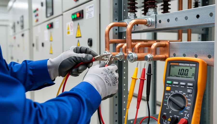
Substation design for utility-scale PV projects demands strict adherence to safety protocols and regulatory standards because medium-voltage equipment presents life-threatening hazards. Arc flash incidents, explosive releases of energy during electrical faults, can cause severe burns, blindness, and fatalities if protection measures fail. Engineers must calculate incident energy levels per IEEE 1584 and NFPA 70E, then specify appropriate personal protective equipment ratings and establish approach boundaries for maintenance personnel. IEEE guidance for safety provides comprehensive methodologies for arc flash hazard analysis and labeling requirements that must appear on all switchgear and transformer enclosures.
High-voltage equipment handling requires specialized training and lockout/tagout procedures compliant with OSHA 1910.269 and NESC Part 4. Grounding and bonding systems must meet IEEE 80 standards for step and touch potential calculations, with ground grid resistance verified through testing before energization. Equipment grounding conductors, bonding jumpers, and surge arresters form an integrated protection scheme that channels fault currents safely and prevents voltage rise on accessible surfaces.
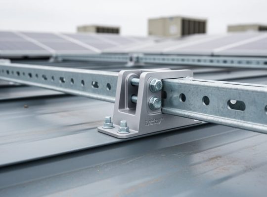
Mandatory compliance extends beyond electrical safety standards to encompass utility-specific interconnection agreements governed by FERC regulations and regional transmission organization rules. These agreements dictate protection relay settings, communication protocols, power quality limits, and testing procedures that cannot be modified without utility approval. NEC Article 690 and 705 establish requirements for photovoltaic system integration, disconnect means, and ground-fault protection that directly affect substation design. While the complexity parallels challenges in B-roof engineering and Q-deck impacts for rooftop installations, substation errors carry far greater consequences because they affect the entire generation facility and grid stability. Similar to precision required in Unistrut mounting for mechanical integrity, electrical design tolerances leave no room for approximation, fault calculations, voltage drop limits, and short-circuit withstand ratings must be verified through simulation and peer review before equipment procurement.
Step-by-Step Process for Designing an MV Substation
Step 1: Conduct Site Assessment and Preliminary Engineering
Site assessment forms the foundation of every successful MV substation design. Begin by commissioning geotechnical borings at the proposed substation footprint to determine soil bearing capacity, groundwater levels, and foundation requirements, these findings directly influence transformer pad design and grounding electrode sizing. Simultaneously, map the site for environmental constraints: wetlands, endangered species habitats, cultural resources, and floodplains require early identification to avoid permitting delays.
Next, coordinate with the utility to confirm the point of interconnection (POI) location, available fault current capacity, and voltage at the delivery point. Request the utility’s interconnection study results and grid infrastructure drawings; these documents reveal existing protection schemes and transformer ratings that constrain your design choices. Conduct preliminary load flow analysis using the PV array’s expected generation profile, ambient temperature data, and the utility’s minimum and maximum operating voltages. This analysis validates your proposed voltage transformation ratio and identifies potential power quality issues.
Layout planning integrates equipment clearances (IEEE 80 grounding, NESC working space), access roads for construction and maintenance, and space for future capacity expansion. Just as thorough roof design review prevents residential solar failures, meticulous site assessment prevents costly substation redesigns during construction.
Step 2: Define Electrical Requirements and System Configuration
Defining electrical requirements begins with calculating the total PV generation capacity by aggregating the nameplate ratings of all inverters connected to the substation. This determines the transformer capacity needed, typically sized at 110-125% of total PV output to accommodate surge conditions and future expansion.
Select the voltage transformation ratio based on the inverter output voltage (commonly 480V or 690V AC) and the utility’s point of interconnection voltage (often 12.47 kV, 34.5 kV, or higher). The step-up transformer converts MV collector voltages to transmission-level voltages for grid delivery.
Choose a substation topology that balances reliability, cost, and operational flexibility. Single-bus configurations offer simplicity and lower cost for smaller installations, while ring-bus or breaker-and-a-half designs provide redundancy and operational flexibility for larger projects exceeding 50 MW.
Specify fault current ratings by analyzing worst-case short-circuit conditions at the point of interconnection. Calculate symmetrical and asymmetrical fault currents to ensure all equipment, circuit breakers, disconnect switches, bus work, and cables, can withstand maximum fault duties without failure. Coordinate these ratings with the utility’s system impedance data and incorporate inverter contribution to fault levels, which differs from traditional synchronous generation.
Step 3: Perform Load Flow and Short-Circuit Analysis
Once you’ve defined your system configuration, the next critical phase is validating your design through electrical modeling. Load flow analysis examines steady-state conditions across the substation under normal and peak generation scenarios. Input your transformer specifications, inverter outputs, and cable impedances into software like ETAP or SKM PowerTools. Run simulations at minimum load, maximum export, and contingency conditions to verify that voltage levels remain within utility-mandated ranges, typically ±5% of nominal voltage at the point of interconnection.
Short-circuit analysis determines fault current magnitudes at every bus location. Model three-phase, line-to-ground, and line-to-line faults to calculate maximum available fault currents. Compare these values against the interrupting ratings of your circuit breakers and the withstand ratings of busbars and cables. If calculated fault currents exceed equipment ratings, you’ll need to upsize breakers, add current-limiting reactors, or reconfigure the system topology.
Pay particular attention to power factor and harmonic distortion. PV inverters inject reactive power and harmonics into the grid, potentially violating utility interconnection agreements. Most utilities require power factor between 0.95 lagging and 0.95 leading, with total harmonic distortion below 5%. Simulate these parameters and specify reactive power compensation or harmonic filters if your results fall outside acceptable limits. Document all simulation results, assumptions, and equipment selections, utilities scrutinize these during interconnection application reviews.
Step 4: Design Protection and Control Systems
Protection and control systems form the nervous system of your substation, detecting faults and isolating equipment before damage occurs. Begin by selecting protective relays based on your short-circuit analysis results. Overcurrent relays (50/51), differential relays (87), and distance relays (21) form the primary protection layers. Each relay must coordinate with upstream and downstream devices to ensure selectivity, only the nearest breaker trips during a fault.
Circuit breakers interrupt fault currents safely. Choose vacuum or SF6 breakers rated for your maximum fault current, with interrupting capacity exceeding calculated levels by 15-20%. Position disconnect switches on both sides of transformers and along bus sections to enable safe maintenance isolation.
SCADA integration allows remote monitoring and control. Specify IEC 61850 or DNP3 communication protocols for relay-to-RTU connectivity. Design redundant communication paths using fiber optics or cellular networks. Your remote terminal unit collects real-time data, voltage, current, power factor, breaker status, and transmits it to the utility operations center.
Coordinate protection settings with the utility’s transmission protection engineers. Your relay timing curves must align with their schemes to prevent misoperation during grid disturbances. Submit coordination studies showing time-current curves for all protective devices from the inverter level through the point of interconnection.
Step 5: Specify Major Equipment and Layout
With technical analyses complete, you now select the physical equipment that forms the substation backbone. Begin with the power transformer, specifying kVA rating based on your maximum PV output plus contingencies (typically 110-125% of inverter nameplate capacity), voltage class (e.g., 34.5 kV primary, 690 V or 12.47 kV secondary), and impedance values that match your short-circuit study results. Choose between oil-immersed or dry-type units depending on environmental regulations and fire codes.
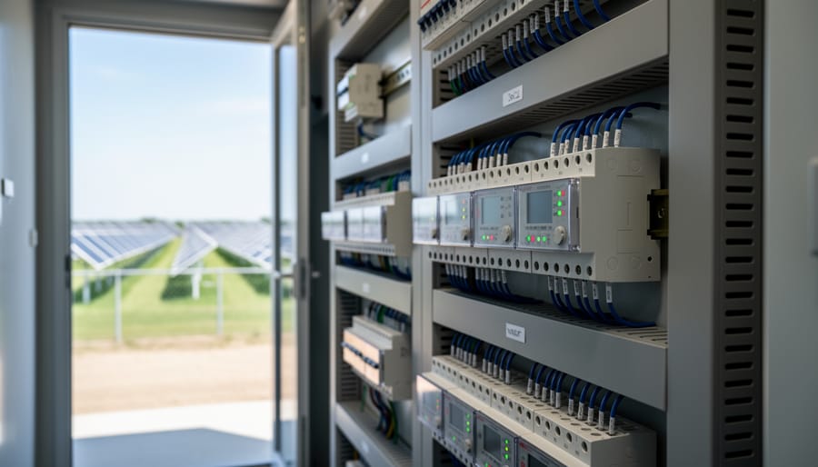
Next, specify medium-voltage switchgear: metal-clad circuit breakers, disconnect switches, and load-break switches rated for your calculated fault currents. Include metering equipment (revenue-grade CT/PT sets compliant with ANSI C12.20 Class 0.2 accuracy) at the point of interconnection. Select auxiliary systems, battery banks for protective relay backup (125 VDC systems are common), HVAC units to maintain equipment rooms within manufacturer temperature limits, and fire suppression tailored to equipment type (CO₂ for control houses, deluge systems for oil transformers if required).
Create single-line diagrams showing all major components, protection devices, and interconnection paths. Develop three-line diagrams detailing phase conductors, neutral, and grounding for construction crews. Draft physical layout drawings that respect electrical clearances per NESC, account for equipment access, and position heavy apparatus near roads for installation logistics. Design the grounding grid using IEEE 80 methodology, calculate grid resistance, touch and step potentials, and specify conductor sizes and ground rod spacing. Integrate lightning protection: surge arresters at transformer terminals, shield wires on overhead lines, and bonding to the substation ground grid.
Step 6: Prepare Construction Documentation and Obtain Approvals
Once the equipment selection and layout are finalized, assembling a comprehensive construction documentation package becomes the bridge between design intent and physical realization. This phase transforms engineering calculations and diagrams into actionable specifications that contractors, suppliers, and regulatory authorities use to build and approve the substation.
Start with a complete drawing set: single-line and three-line diagrams, physical layout plans with coordinates and elevations, grounding grid details, cable routing schedules, and panel arrangements. Supplement drawings with detailed specifications covering equipment performance criteria, installation standards, testing requirements, and quality assurance protocols. Prepare bills of materials listing every component, transformers, switchgear, relays, cables, fasteners, grounding materials, with manufacturer part numbers and quantities.
Concurrently, compile compliance documentation: load flow study results, short-circuit analysis reports, arc flash calculations, environmental impact assessments, and proof of adherence to IEEE, NEC, and utility grid codes. Submit the interconnection application package to the utility, including all technical studies, proposed protection settings, and metering plans. Expect iterative reviews; utilities often request design modifications to align with their system protection philosophy.
Secure local building permits, electrical permits, and environmental clearances by submitting design documents to municipal and county authorities. Coordinate with the utility on commissioning schedules, witness testing requirements, and energization protocols. This documentation becomes the contractual foundation for construction and the reference for all future modifications.
Step 7: Coordinate Interconnection Agreement and Testing Protocols
Coordinating the interconnection agreement and testing protocols transforms your design into a legally binding, operationally ready asset. Begin by finalizing the interconnection agreement with the utility: this document defines your rights and obligations at the point of interconnection, including power quality standards, fault contribution limits, voltage ride-through requirements, and curtailment protocols. Negotiate terms collaboratively, utilities often require specific protection settings, communication interfaces, or reactive power capabilities that may necessitate design adjustments before contract execution.
Simultaneously, establish detailed acceptance testing procedures. Work with the utility to define witness testing protocols: protective relay functionality checks, breaker timing verification, transformer insulation tests, and metering accuracy validation. Document each test sequence, acceptance criteria, and pass-fail thresholds in advance. Develop a commissioning milestone schedule that aligns with utility availability for witness testing, delays here can postpone commercial operation dates.
Plan your energization sequence step-by-step: de-energized checks, partial energization of bus sections, transformer energization under no-load conditions, then full system integration. Coordinate with utility dispatch for switching operations and confirm emergency shutdown procedures. This structured approach ensures smooth handoff from construction to grid synchronization, meeting all contractual obligations before revenue service begins.
Verification, Commissioning, and Readiness for Operation
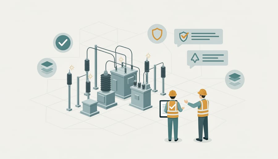
Before a utility-scale PV substation can deliver power to the grid, it must pass rigorous verification protocols that prove the design, installation, and equipment performance meet all contractual and regulatory standards. Factory acceptance tests (FAT) occur at the manufacturer’s facility, where major components, transformers, switchgear, protective relays, are inspected, functionally tested, and certified against design specifications. These tests validate that equipment arrives on-site ready for integration, reducing the risk of field failures and project delays.
Once equipment is installed, site acceptance tests (SAT) verify that the entire substation operates as a unified system under real-world conditions. SAT procedures include insulation resistance testing, transformer turns ratio verification, relay calibration checks, and breaker timing measurements. Engineers measure grounding resistance, confirm SCADA communication, and simulate fault conditions to ensure protective devices respond correctly. Each test result is documented in a commissioning report that serves as evidence of compliance for utility and project stakeholders.
Energization checklists provide step-by-step sequences for safely bringing the substation online. Typical steps include verifying all safety interlocks, confirming circuit breaker positions, energizing the transformer at no-load, and monitoring voltage and frequency during ramp-up. Utility witness testing occurs during this phase: utility engineers observe relay operations, metering accuracy, and compliance with interconnection agreement terms. Only after passing these witnessed tests does the utility authorize grid connection and commercial operation.
The handoff from construction to operations requires comprehensive as-built documentation, single-line diagrams reflecting field modifications, equipment manuals, maintenance schedules, and contact lists for vendors and utility personnel. Operator training sessions familiarize site staff with SCADA interfaces, emergency shutdown procedures, and routine inspection tasks. This training ensures the operations team can safely manage the substation, respond to alarms, and coordinate with utility dispatch centers.
Next steps include establishing an ongoing maintenance program that aligns with manufacturer recommendations and utility requirements. Quarterly inspections check transformer oil levels, breaker operation counts, and relay settings; annual infrared scans detect hot spots before failures occur. Performance monitoring through SCADA tracks energy output, voltage stability, and equipment health, enabling predictive maintenance and rapid troubleshooting. Compliance audits, conducted annually or as mandated by the interconnection agreement, verify continued adherence to IEEE standards, NERC reliability rules, and environmental permits. These audits demonstrate to regulators and stakeholders that the substation operates safely and reliably, supporting the long-term success of the utility PV project.
Frequently Asked Questions About Electric Substation Design for Utility PV
Utility-scale photovoltaic projects demand rigorous substation engineering, and aspiring professionals often face recurring questions about timelines, credentials, and design pitfalls. Below are answers to the most common inquiries that arise during MV substation and interconnection work.
What is the typical timeline for MV substation design?
From preliminary engineering to final approval, expect six to twelve months, depending on project size, utility queue position, and permitting complexity. Interconnection studies alone can take three to six months.
How do interconnection studies affect design decisions?
Studies reveal voltage stability constraints, fault current limits, and required upgrades, which directly dictate transformer sizing, protection schemes, and system topology. Design cannot proceed without incorporating these utility findings.
What certifications or training are recommended?
A Professional Engineer license, IEEE continuing education in power systems, and coursework in grid interconnection standards provide strong foundations. Mose Solar’s online program offers modules on substation design, equipment selection, and utility coordination, often in collaboration with universities to ensure rigorous academic grounding.
What are the most common design mistakes to avoid?
Undersizing transformers for peak capacity, neglecting arc flash analysis, failing to coordinate protection settings with the utility, and overlooking future expansion requirements top the list. Each mistake triggers costly redesigns or safety violations.
Understanding these fundamentals accelerates the learning curve for newcomers to utility solar. The interconnection timeline deserves special attention because utility queues and study schedules often drive the entire project schedule, making early engagement with the utility transmission planning department essential. Designers who wait for interconnection results before starting preliminary layouts risk missing construction windows.
Training pathways vary, but hands-on experience with real utility interconnection agreements and collaboration with experienced engineers prove most valuable. Mose Solar’s educational offerings provide access to case studies, design templates, and mentorship from industry practitioners, bridging the gap between academic coursework and field practice. Partnering with universities ensures that instructional content reflects both theoretical rigor and current industry standards.
Common pitfalls extend beyond technical errors. Communication breakdowns with utility engineers, incomplete as-built documentation, and insufficient witness testing coordination cause project delays as frequently as design flaws. Establishing clear protocols for utility meetings, submittal reviews, and commissioning sign-offs prevents most non-technical issues. Treat every interconnection agreement clause as a design constraint, not an administrative formality.
Mastering electric substation design for utility-scale photovoltaic projects demands rigorous methodology, attention to regulatory frameworks, and disciplined collaboration with utility stakeholders. This step-by-step framework, from initial site assessment through commissioning and verification, provides aspiring photovoltaic professionals with a structured pathway to navigate the complexities of MV substation and interconnection engineering.
Each phase of the design process serves a critical function. Accurate load flow analysis prevents equipment oversizing and cost overruns. Comprehensive protection system design safeguards personnel and assets from fault conditions. Thorough documentation and utility coordination ensure smooth interconnection approvals and timely project completion. Shortcuts or incomplete engineering during any step introduce risks that compromise safety, extend schedules, and jeopardize commercial operation dates.
Safety and compliance remain non-negotiable priorities throughout the design lifecycle. Arc flash hazards, high-voltage equipment handling, and grounding requirements demand strict adherence to IEEE standards, NESC guidelines, and utility interconnection agreements. Regulatory compliance protects teams, secures permits, and maintains grid reliability standards that utilities expect from large-scale solar installations.
Building expertise in substation design requires deliberate skill development. Mose Solar’s online educational program offers structured curriculum covering medium-voltage systems, protection coordination, and grid integration principles. Collaboration with universities provides access to design resources, simulation tools, and mentorship from experienced engineers. Investing in formal education accelerates your capability to design substations that meet technical specifications while advancing the renewable energy transition.