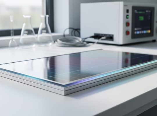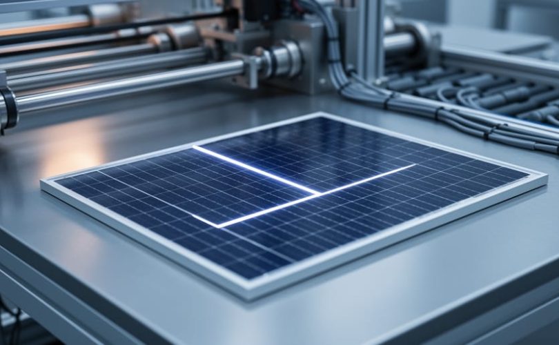
An L-cut is a laser-based cutting step in solar module manufacturing where a cell is separated along a path that turns a corner, forming an L shape, rather than along a single straight line. It’s used within half-cut and multi-busbar cell design, where cells are divided to reduce the current each piece carries. Terminology and parameters vary by manufacturer, so the L-cut isn’t a universal standard, and it’s best understood as one approach among several for shaping and dividing cells.
Why does a cut path matter at all? Every cut exposes a fresh edge, and cell edges influence how a finished module handles mechanical stress, cell layout, and string design. Choosing between a straight half-cut and a more complex path is a real engineering trade-off, not a cosmetic one.
This article explains what an L-cut is, how the process is carried out step by step, and how it compares with standard half-cut approaches. It also covers where the technique shows up in practice, without leaning on unverified performance figures. For specifics on any given product, datasheets and independent test reports remain the reliable sources.
At our site, we pair this kind of plain-language explanation with university collaboration and educational programs, so aspiring photovoltaic professionals can connect module design concepts to the lab and the production line.
What an L-Cut Means in Solar Cell Manufacturing
An L-cut is a cell-separation pattern in which a laser scribes an L-shaped path instead of a single straight line, so the cell is divided along a bent, two-segment route. A conventional half-cut runs one straight line across the middle of a cell and produces two roughly equal rectangles. The L-cut changes the geometry of that path, which can alter the shape of the resulting pieces and how they are arranged in the module layout.
It helps to see where this fits. Cell separation is one step in a broader group of manufacturing choices, and the L-cut is one of several cutting geometries a manufacturer might consider. It is not an industry-wide standard, and terminology varies between companies, so the same pattern may be called something different on another production line. Treat the name as a descriptive label rather than a fixed specification.
Manufacturers may choose a non-straight geometry for reasons tied to cell design, material use, or module layout. These are some of the practical efficiency drivers and trade-offs engineers weigh, though outcomes depend on the specific cell and module.
A few supporting terms make the rest of this article easier to follow:
- L-cut
- A laser-scribed, L-shaped separation path used to divide a solar cell into smaller pieces.
- Half-cut cell
- A cell divided into two smaller pieces, typically along a straight line, so each piece carries less current than the full cell.
- Busbar
- A thin metal strip on the cell surface that collects current from the finer contact lines and carries it to the next cell.
- Laser scribing
- The use of a focused laser to cut a shallow groove along a planned path on the cell.
With those definitions in place, the next section explains why cells are cut at all.
Why Cells Are Cut: The Half-Cut and Multi-Busbar Context
A full-size solar cell carries a relatively high current, and that current has to travel across the cell surface to reach the metal contacts. Resistive loss in those conductors grows with the square of the current, so even a modest reduction in current per piece can meaningfully cut wasted energy. That is the core reason manufacturers divide cells into smaller pieces, whether by a straight half-cut or by other geometries such as an L-shaped path.
Multi-busbar designs approach the same problem from a different angle. Instead of a few wide busbars, the cell carries many thin ones, which shortens the distance current must travel through the cell’s fine contact fingers before it is collected. Shorter paths mean less resistance along the way.
In general terms, the main engineering motivations look like this:
- Smaller cell pieces carry less current, which lowers resistive losses in the interconnects.
- More busbars shorten the collection path across each cell.
- Certain module layouts can improve behavior under partial shading, depending on the circuit design.
- Thinner busbars and smaller pieces can change the mechanical stress distribution within the module.
The two approaches complement each other because each addresses a different part of the loss picture. Cutting reduces the current being carried, while multiple busbars improve how efficiently that current is gathered. Together they give module designers more flexibility in layout and wiring, though the benefits depend on the specific cell, module design and production process involved.
Because results vary between products, it is best not to rely on generalized performance claims. Measured figures belong in manufacturer datasheets and independent test reports, which are the right places to verify how any given module actually performs.
How the L-Cut Process Works Step by Step

Laser Scribing and Mechanical Cleaving
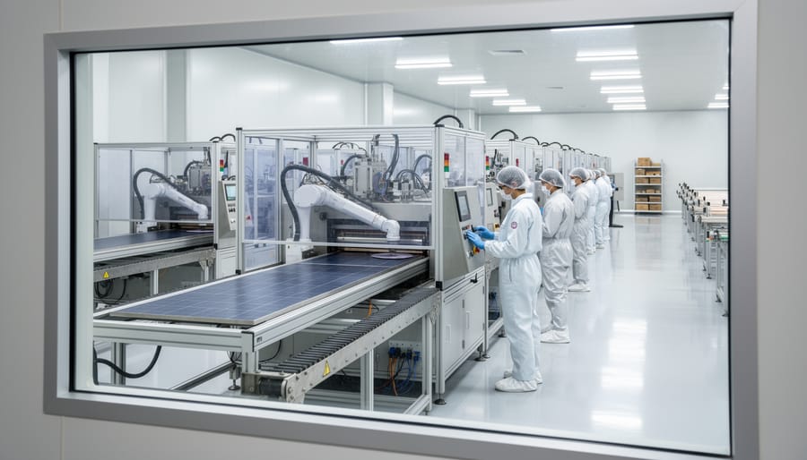
A laser scribing system traces a programmed path across the cell surface and removes a narrow strip of silicon along that line. The result is a shallow groove, not a full cut. The groove acts as a deliberate weak point, so the cell can later be separated in a predictable direction instead of fracturing wherever stress happens to concentrate. In an L-cut, the programmed path follows an L-shaped geometry rather than a single straight line, which puts more demands on motion control and alignment.
Once the groove is in place, the cell is cleaved mechanically. Gentle bending or a controlled break applies stress along the scribe, and the silicon parts along it. Because silicon is brittle, this step works best when the groove is uniform and the applied force is even.
Stress management matters at both stages. A laser introduces heat, and excessive heat can leave a damaged zone near the groove that weakens the edge. The cleaving step can then add mechanical stress to that same region. If scribe depth, laser settings, or breaking force drift out of range, the result can be chipped edges or microcracks that may not show up until later handling.
Specific parameters vary by equipment and manufacturer, so treat the description here as a general outline rather than a recipe.
Edge Quality and Microcrack Considerations
The quality of a cut edge matters because cutting exposes the silicon in a way a finished cell face never is. A laser leaves a thin zone of altered material along the scribe, and a rough or damaged edge can create sites where charge carriers recombine instead of contributing to current. That is a loss mechanism rather than a fixed penalty, and its size depends on the cell design, the laser process, and any treatment applied afterward.
Mechanical reliability is the second concern. Tiny cracks that start at the edge, known as microcracks, can grow under the thermal cycling and handling stresses that modules experience in production and in the field. A groove that is too deep or too uneven makes the cleaving step less predictable, and that raises the chance of defects.
Manufacturers generally address both issues through layered controls:
– Tight process control of laser settings and scribe depth
– Alignment checks so the cleave follows the scribe path
– Inspection steps, such as optical or electroluminescence imaging, to catch damaged pieces before stringing
– Edge treatments or passivation approaches intended to reduce recombination at the cut face
Which of these a given line uses varies by equipment and design, so datasheets and independent test reports are the right places to look for measured outcomes.
L-Cut Compared With Other Cell-Cutting Approaches
The L-cut is best understood by comparing it with the other ways a cell can be divided. The right choice depends on the specific cell format and module design, so treat the points below as general trade-offs rather than fixed rules.
A straight half-cut is the most widely recognized approach. A single laser line runs across the middle of the cell, producing two identical rectangular pieces. The pattern is simple, the laser path is short, and the pieces can be strung in a regular layout. Third-cut and quarter-cut formats follow the same logic with more divisions, creating smaller pieces that carry less current each. They add more cutting passes and more handling steps, and they change how strings are arranged inside the module.
The L-cut departs from these straight-line patterns by using an L-shaped path. That produces pieces of different shapes, which can matter when a module layout needs a particular arrangement or when a cell’s geometry calls for it. The trade-off is added programming and alignment complexity in the laser system.
The components involved change across these approaches:
– Cutting pattern: straight lines are easier to program and verify, while an L-shaped path requires more precise motion control.
– Laser equipment: all of these methods rely on laser scribing, but more complex paths place greater demands on the scanning system and its calibration.
– Stringing layout: piece shape and size determine how tabbing ribbons connect cells, so changing the cut often means adapting the stringer and the module’s electrical layout.
– Busbar configuration: the position and number of busbars on the cell influence where cuts can safely fall, which is especially relevant in multi-busbar designs.
Process complexity, material utilization, and layout flexibility all shift with the chosen pattern. Simpler cuts tend to be easier to control, while more complex geometries can offer layout options at the cost of tighter process management. Because results vary with the cell and module design, readers should consult manufacturer datasheets and independent test reports rather than assuming one approach is universally better.
Where the L-Cut Is Used in Module Production
In module production, the L-cut is best understood as one option on a line that already cuts cells, not a separate product category. Manufacturers building half-cut and multi-busbar designs choose a cutting geometry to suit the cell format, the stringing layout and the equipment they have. The L-shaped path is one such geometry, and whether it appears on a given line depends on those design decisions rather than on any industry rule.
You will see cell cutting most often on lines producing monocrystalline modules, since monocrystalline wafers are the common starting point for half-cut and multi-busbar layouts. It also applies to PERC-based cells, which are cut after cell fabrication, so the passivation structure is already in place. For a deeper look at the cell technology itself, see our overview of Mono PERC modules. The cutting pattern then has to match how the pieces are strung, tabbed and arranged in the module.
Evaluating any of these processes takes a specific skill set: reading process descriptions critically, understanding how cut-edge quality connects to reliability, and checking claims against datasheets and independent test reports. Mose Solar’s online educational program, developed with universities, builds exactly these skills for aspiring PV professionals.
Is an L-cut the same as a half-cut?
Not necessarily. A half-cut divides a cell into two pieces, while an L-cut describes the shape of the cutting path. Terminology varies between manufacturers, so check how a given source defines it.
Does cutting cells reduce their efficiency?
Cutting can introduce edge effects, which manufacturers manage through process control and inspection. Measured results depend on the specific cell and module design, so consult datasheets and independent test reports.
Can any cell type be cut this way?
Suitability depends on the cell design and the equipment used. Manufacturers assess each cell format individually rather than applying one cutting method to all.
Where can I learn more about module manufacturing processes?
Mose Solar’s university-collaborative online educational program covers PV manufacturing concepts in a structured way.

The L-cut is a laser-scribed, L-shaped cutting pattern used to separate solar cells into smaller pieces during half-cut and multi-busbar module manufacturing. The process follows a clear sequence: inspect and sort the cell, scribe along a programmed path, cleave mechanically along the groove, handle the cut pieces carefully, then string them into the module layout. Throughout, scribe depth, alignment, and edge quality need close control.
Keep in mind that the L-cut is one cutting geometry among several, and terminology and process parameters vary between manufacturers. Whether a given approach delivers a real benefit depends on the specific cell and module design. For measured performance, rely on manufacturer datasheets and independent test reports rather than general descriptions like this one.
If you want to build a deeper understanding of PV manufacturing, explore Mose Solar’s online educational program, developed in collaboration with universities.