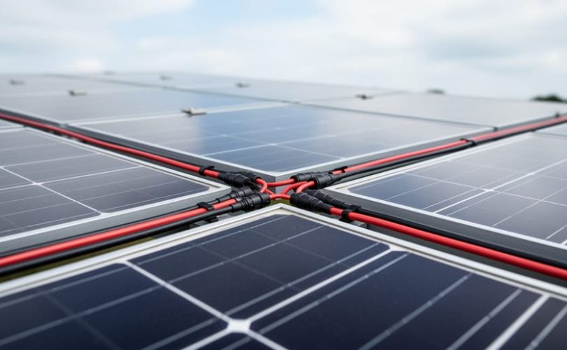
Four solar panels in parallel means connecting all four positive terminals together and all four negative terminals together, so the array’s voltage stays equal to a single panel’s while the current from each panel adds up. Four 12 V panels rated at 5 A each, wired this way, produce a 12 V array delivering 20 A. Wire the same panels in series and you’d get 48 V at 5 A instead.
That difference shapes everything downstream: charge controller selection, wire gauge, fuse sizing, and how the array behaves when one panel is shaded. Parallel wiring tolerates partial shading well, because a dimmed panel doesn’t throttle the output of the others the way it does in a series string. The trade-off is higher current, which demands thicker cable and properly rated protection.
This article explains how voltage and current behave in a four-panel parallel array, walks through a worked example, and covers the connectors, combiner components, and configuration variants you’ll encounter. If you need a refresher on cell and laminate construction first, our guide to PV module basics covers the fundamentals, and the journey from panel to installation shows where wiring decisions fit in a real project.
At Mose Solar, we work with university partners and run educational programs for aspiring photovoltaic professionals, so the explanations here are built to be clear enough for a first-time installer and precise enough for a student of PV systems.
What a 4-Panel Parallel Connection Means
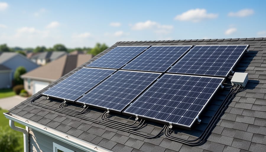
Wiring four solar panels in parallel means joining all four positive terminals together and all four negative terminals together. Each panel then connects directly across the same two points, so the electrical “pressure” (voltage) stays equal to that of a single panel, while the current each panel produces flows into a shared path and adds up.
Series wiring works the opposite way. You link the positive terminal of one panel to the negative terminal of the next, forming a chain. Voltage stacks with every panel added, but current stays at the level of a single panel. Same four panels, same total power, very different electrical behavior.
That core rule, voltage constant and current summed, drives nearly every design decision downstream. It determines wire thickness, fuse size, and whether a charge controller or inverter can safely accept the array’s output. Anyone sizing a small PV system or comparing module datasheets needs to apply it correctly, because the specs printed on a module label mean something different depending on how modules are combined.
A short glossary helps make those datasheet terms clear:
- Parallel connection
- Positive terminals are joined to positive terminals and negative to negative, so voltage stays the same and currents add together.
- Series connection
- Modules are chained positive-to-negative, so voltages add while current stays equal to that of one module.
- Open-circuit voltage (Voc)
- The maximum voltage a module produces with no load attached, used to check that an array stays within equipment limits.
- Short-circuit current (Isc)
- The current a module delivers when its terminals are shorted, used to size wiring and overcurrent protection.
- Maximum power point
- The voltage and current combination at which a module delivers its greatest power under given conditions.
- Combiner box
- An enclosure where the wires from multiple modules or strings are joined, typically with fuses or breakers for protection.
With four panels in parallel, the array’s Voc matches a single panel’s Voc, but its Isc is roughly four times larger. Keeping those two numbers in view is the first step toward a safe, well-matched system.
How Four Panels in Parallel Work Electrically
Voltage, Current, and Power: A Worked Example
Consider four identical panels, each rated at 12 V and 10 A at standard test conditions. These are hypothetical numbers chosen to make the math easy to follow, not a specific product.
Start with one panel. At 12 V and 10 A, it produces 120 W (12 V × 10 A).
Now wire all four in parallel. The positive terminals join together, and the negative terminals join together. Each panel still sees the same two connection points, so the voltage across the array does not change. It stays at 12 V.
Current behaves differently. Each panel feeds its own 10 A into the shared conductors, and those currents add up: 10 A + 10 A + 10 A + 10 A = 40 A. The array now delivers 12 V at 40 A.
Power is simply voltage multiplied by current, so the total is 12 V × 40 A = 480 W. That equals four times the 120 W of a single panel, which is exactly what you would expect from adding four equal sources. If you wired the same panels in series instead, you would get 48 V at 10 A, and the product would still be 480 W. The wiring changes how that power is delivered, not how much exists.
These figures are idealized. Real output moves with sunlight and heat. Lower irradiance reduces current roughly in proportion, while higher cell temperature lowers voltage and trims overall power. Expect a working array to produce less than its nameplate rating for much of the day, and always check the manufacturer’s datasheet for the actual temperature coefficients.
Shading, Mismatch, and Module Design
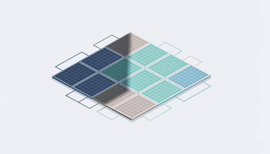
When panels are wired in series, the same current must flow through every module in the string. If one panel is shaded, it limits the current of the whole string, and the entire string’s output can drop sharply. In a parallel array, each panel feeds its own current into a shared pair of conductors, so a shaded panel mostly reduces only its own contribution. The other three keep delivering at nearly full current, which is why parallel wiring is often chosen where shading is unavoidable, such as on boats or RV roofs.
Module design plays a major role here. Most panels divide their cells into substrings, typically three, each protected by a bypass diode. When part of a substring is shaded, the diode lets current route around that section instead of forcing it through the weak cells. This limits power loss and reduces the risk of localized heating, sometimes called hot spots. The way cells are grouped into substrings, and whether they run in vertical or horizontal bands, affects how much output survives partial shading.
Parallel wiring is not a cure-all. A heavily shaded or underperforming panel can still pull down the array’s voltage slightly, and mismatched modules will not all operate at their ideal points. Matching panels by electrical rating helps, and checking the manufacturer’s datasheet for bypass diode details clarifies how a specific module will behave.
Components and Variations of a Parallel Array
Hardware and Safety Components
Wiring four panels in parallel takes more than joining a few wires. The hardware has to handle the summed current safely, and every part of the path needs to be rated for it.
Branch connectors, usually MC4 Y-type or multi-branch versions, merge the four positive leads and the four negative leads into a single pair. For an array this small, they are often enough. When you want per-string protection or easier servicing, a combiner box is the better choice. It collects each panel’s output on a common busbar and houses the fuses or breakers.
Overcurrent protection matters because parallel panels can feed current into a faulted neighbor. If one panel shorts, the other three can push their output backward through it. Fusing each string limits that risk. Cabling must also carry the combined current without overheating or dropping too much voltage, which is why wire gauge is chosen for the summed amperage, not the output of a single panel.
Before building, run through these checks:
- Use panels with matching voltage ratings, ideally the same model.
- Fit an appropriately rated fuse or breaker on each panel’s string.
- Size wire gauge for the total summed current plus a safety margin.
- Confirm the charge controller or inverter can accept the combined current.
- Verify that the layout complies with local electrical codes.
Exact fuse ratings, conductor sizes, and temperature derating factors vary by jurisdiction and by module. Always take them from your local electrical code and the manufacturer’s datasheet, and consult a qualified installer when in doubt.
Series, Parallel, and Series-Parallel Compared
Which arrangement makes sense depends mostly on three things: the voltage your system needs, the input limits of your charge controller or inverter, and how much shading the array will see.
Pure parallel keeps the array at a single panel’s voltage while current quadruples. That suits 12 V battery systems, where the controller expects low voltage, and it handles partial shade well because one dimmed panel doesn’t throttle the others. The trade-off is heavy current, which calls for thicker cables, per-string fuses, and a combiner box.
Pure series does the opposite. Voltage quadruples while current stays at one panel’s level, so thinner wire works and cable losses drop over long runs. It’s the usual choice for grid-tied inverters with high input windows. But a single shaded panel can pull down the whole string, and the summed voltage must stay below the controller’s maximum input rating, including on cold mornings when panel voltage rises.
Series-parallel splits the difference. Two strings of two panels double both voltage and current relative to a single panel, which lets you hit a controller’s sweet spot without extreme current or voltage. For a broader look at how these layouts scale, see this series-parallel comparison.
Always check the controller datasheet and panel specifications before committing to a layout.
Where Parallel Wiring Is Used
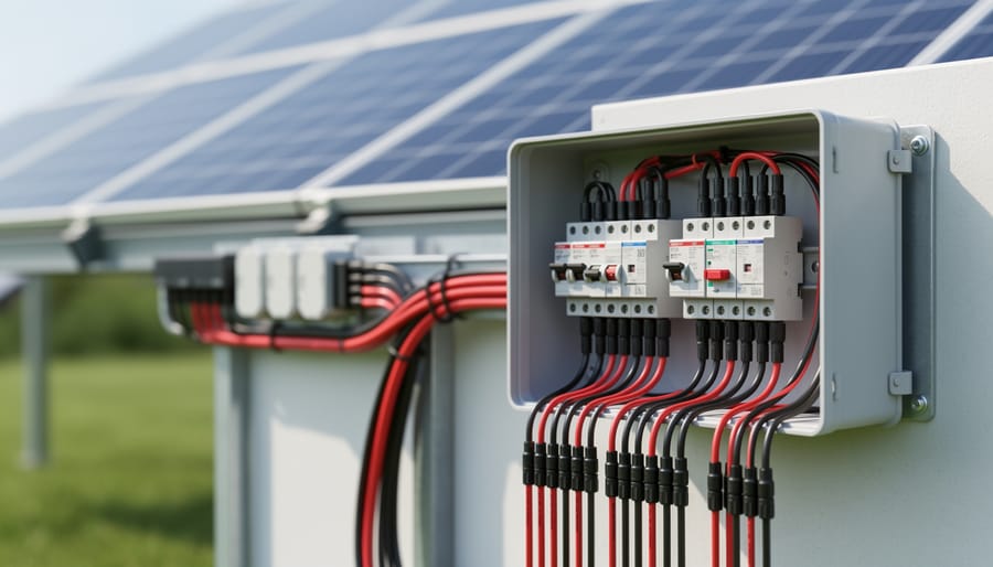
Wiring four panels in parallel shows up most often where the system voltage is low and the priority is simplicity, flexibility, or tolerance of shade. Because parallel wiring keeps the array voltage equal to a single panel’s voltage, it pairs naturally with 12 V equipment, which is why you see it across small off-grid and mobile installations.
Common applications include:
- 12 V battery charging: array voltage matches the battery bank and charge controller input without extra conversion.
- Shade-prone installations: a shaded panel reduces its own contribution without dragging down the whole array, as it can in a series string.
- Mobile systems such as RVs and boats: panels can be mounted wherever roof or deck space allows, and a failure in one doesn’t shut down the rest.
- Small cabins and remote monitoring equipment: low-voltage wiring is easier to manage and expand over time.
- Teaching labs and test benches: students can add or remove a panel and watch current change while voltage holds steady.
The preference for parallel in low-voltage systems comes down to matching equipment ratings. Many 12 V charge controllers, especially simpler PWM models, accept only a limited input voltage. Putting four panels in series could push the array voltage beyond that limit, while parallel wiring keeps it within range. The tradeoff is higher current, so cable gauge, connectors, and overcurrent protection need careful sizing. Always check the controller and panel datasheets and follow local electrical codes.
Higher-voltage systems tend to go the other way. Grid-tied installations, which feed an inverter with a wide, high-voltage input window, usually favor series strings. Raising voltage lowers the current for the same power, which reduces resistive losses in the cabling and allows thinner, cheaper wire over long runs between the array and the inverter. For that reason, a rooftop array feeding a string inverter is rarely wired as a pure parallel group of four.
In practice, many designers land on a hybrid. Two strings of two panels (series-parallel) can balance voltage and current to suit a particular controller or inverter. The right choice depends on the equipment’s input limits, the cable distances involved, and how much shading the site experiences, which is exactly the kind of system-level reasoning covered in introductory PV design training.
Common Questions About Wiring Four Panels in Parallel
Parallel wiring raises practical questions fast, so here are the ones that come up most often. For any real installation, check the module datasheet and local electrical code, and consult a qualified installer.
Can I mix different panel models in parallel?
It is possible, but it works best when the panels have closely matched voltage ratings. In parallel, the array sits at one shared voltage, so a panel with a lower operating voltage drags the others away from their best point and wastes some output. Panels with different current ratings are less of a problem, since current simply adds up, which is why cell type choice and matched specifications matter when you plan an array.
Do I need fuses with four panels?
Often, yes. When several panels feed one bus, a fault in one can be backfed by current from the others, so individual protection is commonly required. The datasheet lists the maximum series fuse rating, and local code decides the rest, so confirm both before you wire.
Does parallel wiring produce more power than series?
No. Total power is the sum of each panel’s output either way. Parallel keeps voltage the same and adds current, while series adds voltage and keeps current the same, so the difference lies in cable sizing, controller compatibility, and shading behavior.
Which is better for a 12 V battery bank?
Parallel is a natural fit for nominal 12 V panels, because it holds the array voltage in the range the battery and charge controller expect. Check the controller’s maximum input current to confirm it can handle the combined amperage.
Wire size follows the same logic. Because current adds up in parallel, the main run from the combiner to the controller must carry the full combined current, plus a safety margin. A qualified installer can size it using the datasheet’s short-circuit current and your local code.
Wiring four solar panels in parallel keeps the array voltage equal to a single panel’s while the currents add together. That one rule explains most of the design choices that follow. Whether parallel, series, or a series-parallel mix is the right fit depends on your system voltage, how much shading the array will see, and the input limits of your charge controller or inverter.
Those decisions start at the module level. Open-circuit voltage, short-circuit current, and bypass diode layout are all set during Solar PV Module Development, and they determine how modules can safely be combined into an array. Reading the datasheet carefully is the first step of any sound design, and it fits naturally into your overall project development timeline.
If you want to go deeper into array sizing, protection, and system design, Mose Solar’s online educational program, developed in collaboration with universities, covers these fundamentals step by step.