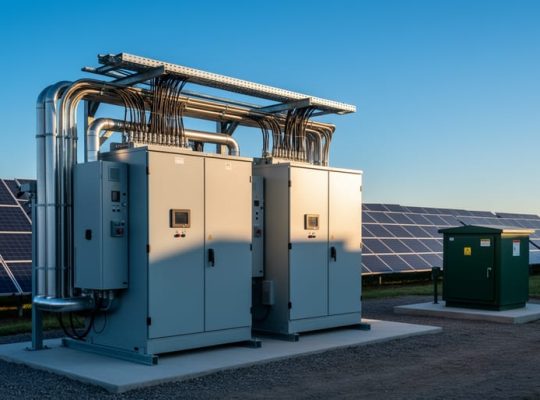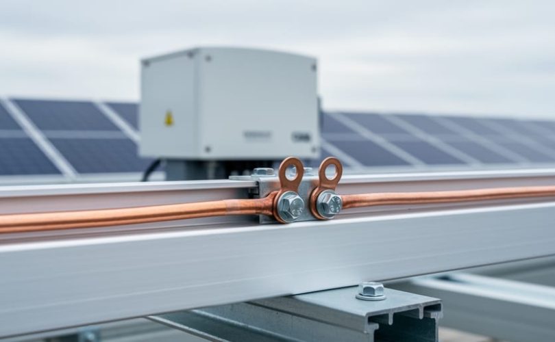
Bonding protection establishes low-impedance electrical connections between all metallic components in a photovoltaic system, ensuring they share the same electrical potential and preventing dangerous voltage differences during fault conditions or lightning strikes. This protective function works by creating deliberate pathways that allow fault currents to flow safely to ground, enabling overcurrent devices to trip quickly and reducing the risk of electric shock, equipment damage, and fire hazards.
While grounding provides a reference to earth potential, bonding interconnects conductive surfaces that people might touch or that could become energized during faults. In PV installations, proper bonding connects module frames, mounting structures, array racking, combiner boxes, inverters, and other metallic enclosures into an equipotential network. Without these connections, lightning-induced currents or insulation failures can create voltage gradients across metal components, turning touchable surfaces into shock hazards and exposing sensitive electronics to destructive potential differences.
The distinction matters in practice. A PV array might have an adequate grounding electrode system yet still pose serious safety risks if bonding jumpers between rack sections are missing or corroded. Equipment bonding conductors must be sized according to the upstream overcurrent protection device, typically matching or exceeding the associated circuit conductors as specified in electrical codes. Material selection is equally critical: bonding hardware must resist outdoor environmental degradation while maintaining reliable electrical continuity over decades of service life.
Installers and system designers frequently underestimate bonding complexity, particularly in large commercial arrays where hundreds of individual connections form the protective network. Each connection point represents a potential failure mode if improperly torqued, incompatible materials create galvanic corrosion, or grounding washers fail to penetrate anodized surfaces. Understanding these requirements isn’t optional for professionals entering the field. Through our collaboration with universities and educational programs, we’ve seen firsthand how thorough bonding knowledge separates competent installers from those whose systems pose latent risks.
What Bonding Protection Accomplishes in Photovoltaic Installations
Bonding protection serves three primary purposes in photovoltaic installations: eliminating dangerous voltage differences between metallic components, providing safe paths for fault currents to flow, and protecting against transient voltage surges from lightning activity. When properly implemented, bonding creates an equipotential plane where all exposed metal surfaces within the array remain at the same electrical potential, preventing the dangerous condition where someone could contact two surfaces at different voltages simultaneously.
The equipotential bonding function connects module frames, mounting rails, support structures, equipment enclosures, and other conductive components into a unified network. Without this connection, normal system operation or external events like nearby lightning strikes can create voltage differences between separate metal parts. These voltage differences present serious shock hazards to installers and maintenance personnel who might touch two different components at once. Proper bonding ensures that no significant potential difference exists between any accessible metallic parts within the PV system.
Beyond eliminating touch voltage hazards, bonding provides the low-impedance return path necessary for overcurrent protective devices to operate correctly during ground faults. When insulation fails or a conductor contacts a grounded metal surface, fault current must flow back to the source through the equipment grounding system. The bonding network carries this fault current, and only when sufficient current flows will circuit breakers or fuses activate to isolate the faulted circuit. Inadequate bonding creates high-impedance paths that may allow dangerous fault currents to persist without tripping protective devices.
The protective function extends to lightning events and induced surges. Direct lightning strikes inject massive currents into whatever they contact, while nearby strikes induce voltage surges through electromagnetic coupling. A well-bonded system distributes these currents across multiple parallel paths rather than forcing them through a single conductor, reducing peak voltages at any given point. This multi-path approach also helps dissipate induced voltages before they reach sensitive electronic components. Proper PV grounding and bonding design recognizes these transient threats and sizes bonding conductors to handle both steady-state fault currents and the brief but intense currents from lightning activity.
Bonding protection works continuously throughout the system’s operational life, maintaining safety even as connections age and environmental conditions change. Regular verification confirms that bonding integrity remains intact and that all connections maintain the low resistance necessary for effective protection.
Components and Materials Required for Effective Bonding
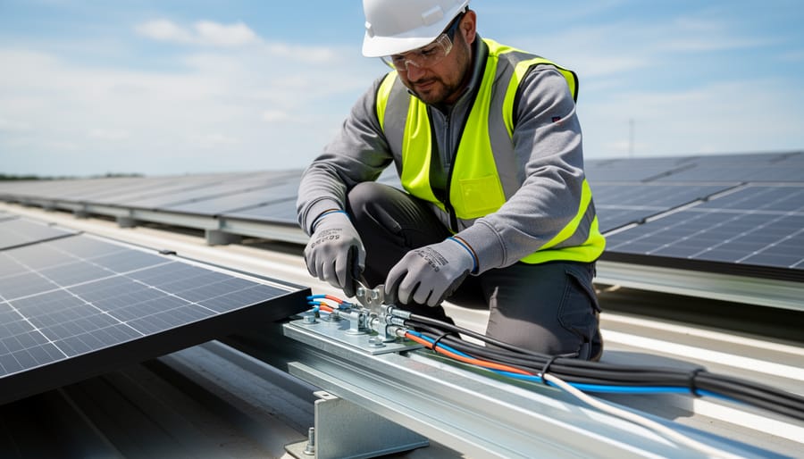
Equipment Bonding Conductors (EBCs)
Equipment bonding conductors serve as the electrical backbone connecting all non-current-carrying metallic components in a PV system back to the grounding electrode system. These conductors create a permanent, low-impedance path that ensures module frames, mounting rails, inverter enclosures, and other metallic parts remain at the same electrical potential during both normal operation and fault conditions.
The National Electrical Code establishes minimum sizing requirements for EBCs based on the rating of the overcurrent protective device ahead of the equipment being protected. For most residential and small commercial PV systems, this typically means a minimum #6 AWG copper or #4 AWG aluminum conductor. Larger systems with higher fault current potential require correspondingly larger bonding conductors. The sizing calculation must account for the largest overcurrent device in the circuit that could supply fault current to the bonded equipment.
Material selection matters beyond just conductor size. Copper offers superior conductivity and corrosion resistance, making it the preferred choice for most applications. Aluminum conductors are acceptable but require careful attention to termination methods and anti-oxidant compounds to prevent degradation at connection points. Mixing dissimilar metals in direct contact creates galvanic corrosion risk, so connections between copper and aluminum components need listed bimetallic connectors or separating washers.
The routing of EBCs requires physical protection from mechanical damage while maintaining electrical integrity. Conductors should follow the shortest practical path to the grounding electrode system, avoiding sharp bends that could compromise the conductor or create high-impedance points. Where EBCs pass through metal enclosures or structural members, protect them with grommets or bushings to prevent insulation damage.
Bonding Jumpers and Connection Hardware
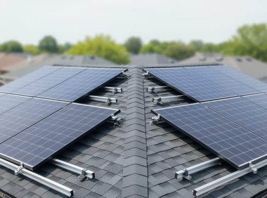
Bonding jumpers serve a specialized function where standard equipment bonding conductors cannot maintain continuous electrical connection. These flexible or semi-rigid connectors bridge sections of racking that must accommodate thermal expansion, structural movement, or intentional mechanical separation. Without properly installed jumpers, expansion joints and disconnected racking segments create breaks in the equipotential plane, leaving isolated metal components at different electrical potentials during fault conditions or lightning events.
Approved connection methods fall into three primary categories, each with distinct applications. Listed grounding hardware, including compression lugs, lay-in lugs, and spring-loaded grounding clips, provides reliable connections when installed per manufacturer specifications. These listed devices undergo testing to verify mechanical and electrical performance under temperature cycling and environmental exposure. Compression fittings create permanent connections by mechanically deforming a connector around the conductor and attachment point, requiring proper crimping tools and correct die selection for the conductor size. Exothermic welding uses a controlled chemical reaction to create a molecular bond between conductor and bonding surface, producing connections with conductivity equal to the base metal itself.
Bonding jumpers must withstand mechanical stress from wind loads and thermal cycling while maintaining low electrical resistance. Flexible braided copper jumpers accommodate movement at expansion joints. Solid copper jumpers suffice for fixed connections across structural gaps. All jumpers require corrosion-resistant terminations, and connections to dissimilar metals need appropriate transition hardware to prevent galvanic corrosion. Proper torque application prevents both under-tightened connections that increase resistance and over-tightened connections that damage hardware or conductors.
Installation Methods and Best Practices
Module Frame and Racking Bonding
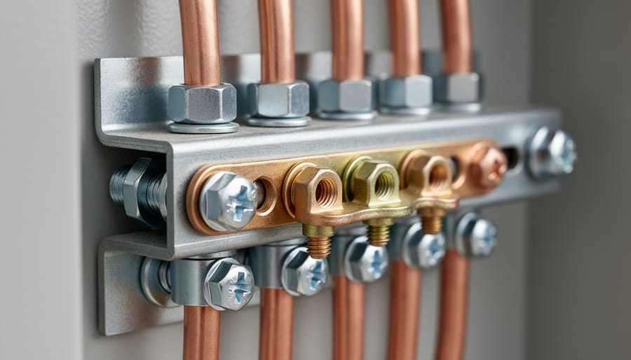
Modern PV modules typically feature pre-drilled holes or grounding clips that facilitate bonding to mounting rails. The bonding path starts at each module frame, extends through the racking structure, and terminates at the equipment grounding conductor. Proper roof design impacts how effectively this bonding network can be implemented across the array.
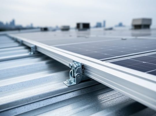
Contemporary racking systems often incorporate integrated bonding features such as serrated washers or bonding clips that penetrate surface oxidation and create metal-to-metal contact when properly torqued. These listed components establish electrical continuity without requiring separate bonding jumpers between each module and rail. When using integrated bonding hardware, verify that the manufacturer’s installation torque specifications are followed precisely, insufficient torque prevents adequate contact, while excessive torque can damage threads or grounding teeth.
Older racking systems and some retrofit installations require supplemental racking bonding using discrete bonding jumpers or grounding lugs. These connections must bypass painted surfaces, anodized coatings, or powder coating that would otherwise create resistive barriers. Wire brush the contact area to bare metal before installing bonding hardware, and apply anti-oxidant compound on aluminum connections to prevent long-term degradation.
Rail sections joined with splice connectors need bonding jumpers across the joint to maintain structural continuity and ensure the entire racking network functions as a unified equipotential plane. Standard structural bolts alone don’t guarantee electrical continuity, especially in outdoor environments where corrosion develops at interfaces. Verify continuity with low-resistance measurements during installation and document connection points for future inspection.
Inverter and Combiner Box Bonding
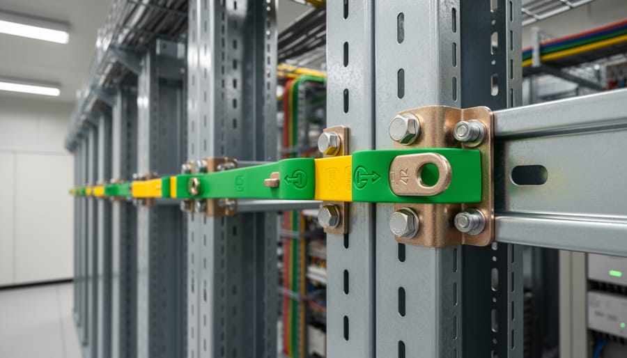
Inverters, combiner boxes, and disconnect switches house critical electrical components within metallic enclosures that require proper bonding to the equipment grounding system. Each enclosure must have a dedicated equipment bonding conductor connection point, typically a grounding lug or bus bar rated for the conductor size specified by code. The bonding conductor connects to this point using compression terminals or listed grounding hardware, creating a continuous low-impedance path back to the system grounding electrode.
Power conversion equipment presents unique bonding challenges due to the presence of both DC and AC circuits. The inverter enclosure must be bonded on both the DC input side and AC output side, with bonding conductors sized according to the largest overcurrent protective device protecting each circuit. Combiner boxes consolidate multiple source circuits and require bonding that accounts for the cumulative current-carrying capacity of all inputs.
Surface preparation matters considerably for these connections. Paint, powder coating, or anodizing at the bonding lug mounting point creates resistance that degrades the bonding path. Manufacturers often provide unpainted bonding points or specify locations where coating should be removed before attaching bonding conductors. Clean metal-to-metal contact ensures the connection can handle fault currents without excessive voltage drop.
When multiple enclosures mount on a common support structure or within the same equipment area, bonding jumpers between adjacent boxes supplement the main equipment grounding conductor, creating redundant paths that enhance fault current handling and reduce potential differences during electrical events.
How Bonding Protection Integrates with Grounding and Lightning Protection
Bonding protection functions as part of a three-component protective framework alongside grounding and lightning protection, with each element serving distinct yet interdependent roles. Bonding establishes equipotential conditions by electrically connecting all metallic components, module frames, racking, inverter enclosures, and conduit, so that no voltage difference exists between them during normal operation or fault conditions. Grounding then ties this equipotential network to earth potential through grounding electrodes, providing a reference point and a path for fault currents to flow safely to earth. Lightning protection systems add surge arresters and air terminals designed to intercept strikes and channel their energy harmlessly away from sensitive electronics.
The integration works through shared conductive paths. When a lightning strike or electrical fault occurs, current seeks the lowest-impedance route to ground. Proper bonding ensures multiple parallel paths exist throughout the metallic structure, distributing surge energy across the entire framework rather than forcing it through a single conductor or component. Without adequate bonding, portions of the system can rise to different potentials during a transient event, creating destructive voltage differences that arc across gaps, damage semiconductors, or present shock hazards to personnel.
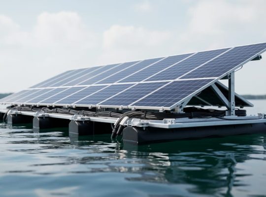
This protective strategy extends to floating PV installations where conventional earth grounding presents unique challenges. Implementing safe grounding methods in such environments requires careful consideration of water conductivity and alternative reference electrodes, but the bonding principles remain unchanged, all metallic parts must maintain electrical continuity to form a unified equipotential zone.
Lightning protection effectiveness depends directly on bonding quality. A strike dissipating through a well-bonded system follows numerous low-resistance paths simultaneously, reducing peak voltage rise at any single point. Corroded connections, missing jumpers, or isolated metallic sections force current through narrower channels, elevating local voltages and increasing the likelihood of equipment damage or side flashing between components.
The interdependence means that neglecting any single element compromises the entire protective scheme. Grounding without comprehensive bonding leaves isolated metal at hazardous potentials. Bonding without proper earth grounding provides no ultimate discharge path for fault energy. Lightning protection systems without both bonding and grounding cannot effectively dissipate the massive transient currents they intercept.
Common Bonding Deficiencies and Their Consequences
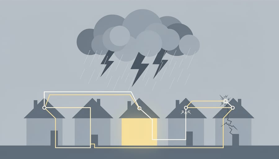
Bonding deficiencies represent some of the most serious yet preventable problems in PV installations. Understanding these failures helps installers and inspectors identify vulnerabilities before they lead to safety hazards or equipment damage.
Loose or Inadequate Connections
Connections that appear secure during initial installation can loosen over time due to thermal cycling, vibration, or improper torque application. A loose bonding connection creates high resistance in the fault current path, potentially allowing dangerous voltages to persist on equipment frames during ground faults. Without a reliable low-impedance path, overcurrent protection devices may fail to trip, leaving energized metal components that pose shock hazards to maintenance personnel.
Corroded Terminations
Corrosion at bonding terminations progressively increases resistance and can eventually create open circuits in the protective system. Dissimilar metals in direct contact accelerate galvanic corrosion, particularly in coastal or industrial environments. Corroded connections compromise both normal fault protection and lightning surge dissipation, leaving equipment vulnerable to transient overvoltages that can damage inverters and monitoring systems.
Missing Bonding Jumpers
Racking systems with expansion joints, hinged access panels, or sectioned arrays require bonding jumpers to maintain electrical continuity. Missing jumpers create isolated metal sections that can develop dangerous potential differences during fault conditions or lightning events. This isolation prevents proper equipotential plane formation, defeating the fundamental purpose of bonding protection.
Improper Conductor Sizing
Bonding conductors undersized for expected fault currents create bottlenecks in the protective system. While the conductor may appear adequate for normal conditions, it can fail catastrophically during fault events, melting or vaporizing under high current loads. This failure eliminates protective bonding exactly when it’s most critical.
Paint and Coating Interference
Powder coating, anodizing, or paint on module frames and racking creates insulating barriers that prevent metal-to-metal contact. Relying on mechanical pressure alone through these coatings results in high-resistance connections that compromise bonding effectiveness. Proper installation requires removing coatings at connection points or using listed hardware designed to penetrate protective finishes.
Each of these deficiencies transforms bonding protection from an effective safety system into a liability, creating false confidence while leaving personnel and equipment exposed to preventable hazards.
Code Requirements and Standards Governing Bonding Protection
Bonding protection requirements for photovoltaic systems are established through a framework of electrical codes, industry standards, and equipment listing protocols that vary by jurisdiction and installation type. Understanding which codes apply to your project, and staying current with their evolving requirements, is essential for both safety and regulatory compliance.
In the United States, the National Electrical Code (NEC) provides the foundational requirements for PV system bonding. Article 690 specifically addresses solar photovoltaic systems and establishes bonding obligations for exposed non-current-carrying metal parts including module frames, mounting structures, equipment enclosures, and raceways. The NEC requires that these components be bonded together and connected to the grounding electrode system using equipment grounding conductors sized according to Article 250. Section 690.43 addresses equipment grounding and bonding, while Section 690.47 covers grounding and bonding requirements for systems with alternating-current and direct-current portions. Local amendments to the NEC are common, so the adopted code edition and any jurisdiction-specific modifications determine what actually applies on-site.
Internationally, IEC 62305 series standards address lightning protection systems and include bonding requirements to create equipotential conditions. IEC 60364 covers electrical installations in buildings and establishes protective bonding principles applicable to PV arrays. The specific IEC standards referenced depend on the installation location and whether the system is building-integrated or ground-mounted.
UL standards such as UL 2703 (Mounting Systems, Mounting Devices, Clamping/Retention Devices, and Ground Lugs for Use with Flat-Plate Photovoltaic Modules and Panels) establish requirements for listed grounding hardware. Using UL-listed bonding components helps ensure compatibility with module and racking systems while meeting code-required performance criteria.
Beyond these primary documents, regional codes, utility interconnection standards, and authority-having-jurisdiction requirements may impose additional bonding specifications. Professional system designers must reference the current editions of all applicable codes for their specific project jurisdiction rather than relying on generalized guidance or outdated standards. Codes evolve as installation practices and equipment technology advance, making ongoing education critical for maintaining compliance throughout a career in PV system design and installation.
Testing and Verification of Bonding System Integrity
Verifying bonding integrity requires systematic testing procedures that confirm all metallic components maintain proper electrical continuity. Three primary methods establish whether a bonding system meets design specifications: visual inspection, continuity testing, and resistance measurement. Each approach serves a distinct purpose in confirming installation quality and ongoing system safety.
Visual inspection identifies obvious deficiencies before electrical testing begins. Inspectors examine all bonding connections for secure torque, intact hardware, and freedom from corrosion. Paint, powder coating, or anodization between contact surfaces signals potential problems requiring remediation. Missing bonding jumpers at expansion joints or between separated racking sections represent critical failures that compromise the entire protective scheme.
Continuity testing uses a digital multimeter or specialized bonding tester to verify complete electrical paths between components. This test confirms that current can flow from remote array sections back to the main grounding point without interruption. Testing proceeds systematically from the farthest module frames through racking systems to inverters and grounding electrodes, identifying any breaks in the bonding network.
Resistance measurements quantify connection quality beyond simple continuity. Industry practice typically calls for bonding connections to exhibit resistance below 0.1 ohms, though specific thresholds may vary based on system design and applicable codes. Lower resistance values indicate superior connections with minimal impedance to fault current flow. Measurements exceeding acceptable limits require inspection and correction of affected connections.
Initial testing occurs after installation completion, before system energization. This baseline verification confirms that bonding meets design specifications from the outset. Retesting becomes necessary following any maintenance work that disturbs bonding connections, after known lightning strikes to the array or nearby structures, and as part of periodic inspection protocols. Some jurisdictions mandate annual testing for commercial installations, while residential systems benefit from testing every three to five years or whenever performance anomalies suggest protective system degradation.
Documentation of all test results establishes a performance history that reveals developing problems before they compromise safety or equipment protection.
Educational Resources for PV Professionals
Mastering bonding protection requires more than theoretical knowledge, it demands practical understanding of system design, component selection, and installation techniques that evolve with industry standards. Mose Solar addresses this need through collaborative development of comprehensive online educational programs with university partners, creating curriculum that bridges academic rigor with real-world application.
These programs offer aspiring PV professionals structured learning paths covering the full spectrum of protective system design, from fundamental bonding principles through complex lightning protection integration. Coursework emphasizes hands-on knowledge of current industry standards, code compliance, and field-proven installation methods rather than abstract theory alone.
The educational content reflects ongoing collaboration between industry practitioners and academic institutions, ensuring that program material remains aligned with evolving best practices and regulatory requirements. This partnership approach helps professionals build competency in areas where inadequate training often leads to installation deficiencies, proper conductor sizing, connection torque specifications, corrosion prevention, and system verification testing.
For professionals seeking to strengthen their expertise in grounding, bonding, and lightning protection design, these programs provide accessible pathways to developing the specialized knowledge that distinguishes competent installers from those simply meeting minimum requirements.
Frequently Asked Questions About Bonding Protection
What is the difference between bonding and grounding?
Bonding connects all non-current-carrying metal parts together to create an equipotential plane, eliminating voltage differences between components. Grounding connects this bonded system to the earth electrode, establishing a reference to earth potential and providing a path for fault currents to flow safely.
Can I rely on mechanical connections for bonding?
No. While mounting hardware creates mechanical connections, these are not engineered or tested for electrical continuity. Paint, anodization, corrosion, and thermal expansion can compromise conductivity. Always use listed bonding hardware designed specifically for electrical grounding purposes.
How often should bonding connections be inspected?
Inspect bonding connections immediately after installation, then annually as part of routine system maintenance. Additional inspection is warranted after lightning events, significant weather damage, or any work that disturbs grounding connections. Check for corrosion, looseness, and physical damage at all termination points.
What size bonding conductor do I need?
Conductor sizing depends on the largest overcurrent protection device in the circuit and must meet requirements in the applicable electrical code for your jurisdiction. Equipment bonding conductors typically range from 6 AWG to 2/0 AWG copper for most residential and commercial installations, with larger conductors required for utility-scale systems.
These questions reflect concerns installers encounter when designing and implementing bonding protection systems. The distinction between bonding and grounding creates confusion because both involve connecting metal parts, yet they serve different protective functions. Understanding this difference helps installers recognize why both are required and how they complement each other in comprehensive system protection.
The mechanical connection question arises because racking systems physically connect array components, creating a tempting shortcut. This approach fails in practice. Anodized aluminum, powder-coated steel, and even clean metal surfaces develop oxide layers that impede current flow. Temperature cycling expands and contracts connections, loosening threads and opening gaps. Listed bonding hardware overcomes these challenges through specific features: teeth that penetrate coatings, spring washers that maintain pressure, and corrosion-resistant materials that ensure long-term conductivity.
Inspection frequency balances practical maintenance schedules against the reality that connections degrade over time. Annual checks catch gradual deterioration before it creates hazards. Lightning events justify immediate inspection because surge currents can vaporize undersized conductors, loosen compression fittings, or damage connection points. Even when no visible damage appears, resistance measurements verify that bonding paths remain intact.
Conductor sizing presents a straightforward engineering calculation, yet installers sometimes undersize bonding conductors to save cost or simplify installation. This creates dangerous conditions. During ground faults, bonding conductors must carry full fault current without overheating or failing, allowing overcurrent devices to operate properly. Undersized conductors may burn open, creating floating voltages on equipment and defeating the entire purpose of bonding protection. The applicable electrical code provides sizing tables based on overcurrent device ratings, removing guesswork from the equation.
Corrosive environments demand additional attention. Coastal installations face salt spray, agricultural sites encounter fertilizers and chemicals, and industrial locations expose equipment to various corrosive agents. Stainless steel hardware, tin-plated copper lugs, and anti-oxidant compounds protect connections in these conditions. Bimetallic junctions between aluminum racking and copper bonding conductors require listed compression connectors or special compounds that prevent galvanic corrosion. Where corrosion risk is severe, periodic inspection frequency should increase beyond the annual baseline.
Bonding protection stands as a non-negotiable foundation of PV system safety, quietly performing the critical work of equalizing electrical potentials and providing fault current paths that prevent equipment destruction and protect human life. When executed properly, with appropriate materials, secure connections, and verified continuity, bonding systems deliver decades of reliable protection. When compromised by corroded terminals, missing jumpers, or undersized conductors, they create latent hazards that may not manifest until a fault or lightning event exposes the weakness.
The difference between adequate and deficient bonding often comes down to installation discipline: torquing connections to specification, preparing surfaces for metal-to-metal contact, using listed hardware rated for the environment, and documenting as-built configurations. These details matter because bonding operates in the background, unseen until the moment protection is needed most.
For professionals committed to designing and installing systems that perform safely over their full operational life, comprehensive education in grounding, bonding, and lightning protection is essential. Mose Solar collaborates with universities to develop online programs that build this expertise, equipping aspiring PV professionals with practical knowledge grounded in current codes and field-proven practices. Mastering bonding protection isn’t just about meeting minimum requirements, it’s about understanding why each connection matters and building systems that protect reliably, year after year.