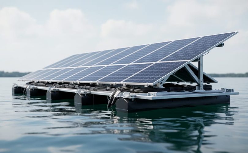
Electrically floating a photovoltaic system means intentionally isolating both the positive and negative DC conductors from ground, creating no direct electrical path between the PV array and earth potential. This configuration is not merely recommended for floating solar installations mounted on water bodies; it is a mandatory safety requirement under most electrical codes governing water-based PV systems. Without proper electrical isolation, fault currents can energize the surrounding water, creating life-threatening shock hazards for maintenance personnel, swimmers, and wildlife.
The physics behind this requirement is straightforward. Water conducts electricity, and any ground fault in a conventionally grounded PV system can send current through the water itself, potentially electrifying a large area around the installation. By maintaining electrical isolation from ground on both DC poles, floating PV systems ensure that a single ground fault cannot establish a current path through the water. The system remains safe until a second fault occurs, at which point ground fault detection equipment triggers a shutdown.
For engineers and installers transitioning from land-based to water-based solar, understanding electrical floating represents a fundamental shift in grounding philosophy. Traditional rooftop and ground-mount systems typically connect one DC conductor to earth for lightning protection and fault detection. Floating solar inverts this approach, requiring insulation monitoring devices, specialized inverters with galvanic isolation, and rigorous testing protocols to verify and maintain isolation integrity throughout the system’s operational life.
The complexity increases when factoring in real-world challenges: humidity, water ingress, UV degradation of insulation materials, and the movement of floating structures. Each element demands careful attention during design and installation to preserve the electrical isolation that keeps these systems safe.
Understanding Electrical Floating in PV Systems
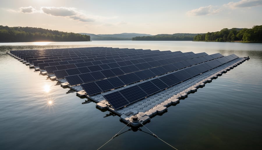
The Water Challenge: Why Floating PV Is Different
Water introduces electrical complexities that land-based PV systems never encounter. Unlike soil, which can vary in conductivity but remains relatively stable, water bodies present a dynamic conductive medium that surrounds and interacts with every structural element of a floating array.
Fresh water typically exhibits conductivity ranging from 50 to 1,500 microsiemens per centimeter, while brackish and saltwater environments can exceed 50,000 microsiemens per centimeter. This conductivity creates multiple current pathways between the PV array and the water body itself. Any component that loses insulation integrity or develops even microscopic contact with water can establish a ground path, compromising the electrically floating status and creating shock hazards for maintenance personnel working on platforms.
The situation becomes more complex because water conductivity fluctuates with temperature, dissolved mineral content, organic matter, and seasonal variations. A system that maintains proper isolation during dry months might develop leakage paths when conductivity rises during monsoon seasons or algae blooms. This variability demands continuous isolation monitoring rather than one-time verification.
Corrosion accelerates dramatically in water-based environments, particularly where dissimilar metals connect in the presence of an electrolyte. Even with protective coatings, mounting hardware, cable glands, and junction boxes face constant exposure to humidity and occasional submersion. As protective layers degrade, small currents can flow between array components and water, eroding both electrical isolation and physical integrity. Stray currents of just milliamperes can cause significant galvanic corrosion over months, eventually creating full ground faults that compromise system safety and performance.
Grounded vs. Ungrounded (Floating) PV Arrays
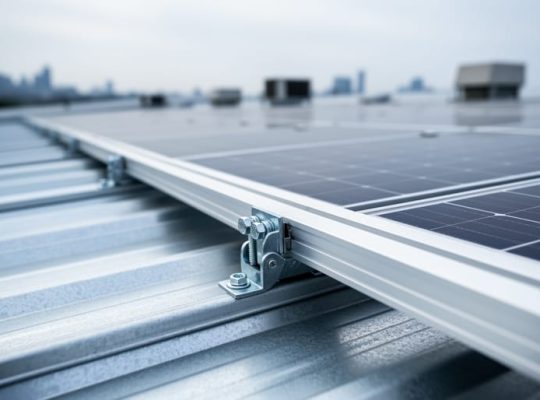
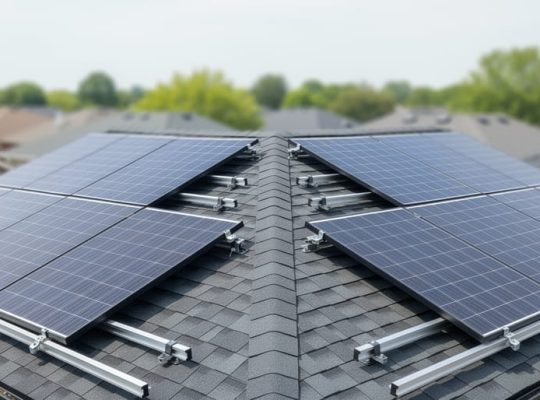
In traditional ground-mounted systems, one DC conductor connects directly to earth ground, establishing a fixed voltage reference. This grounded configuration simplifies fault detection, any unintended current flow to ground triggers protective devices immediately. Most residential and commercial rooftop installations use this approach because the mounting structure already provides a reliable earth connection.
Electrically floating (ungrounded) arrays take a different approach: neither the positive nor negative DC conductor connects to earth ground. Instead, the entire PV array “floats” at an undefined potential relative to earth. This configuration doesn’t mean the system lacks safety grounding, equipment grounding conductors still bond all metal frames and enclosures together and to earth. What floats is the electrical circuit itself, not the physical equipment.
| Characteristic | Grounded Configuration | Floating Configuration |
|---|---|---|
| Voltage Reference | One conductor at earth potential | No conductor at earth potential |
| Fault Detection | Immediate trip on first ground fault | Monitors insulation resistance continuously |
| System Continuity | Shuts down on ground fault | Can operate through first fault |
| Typical Applications | Rooftop, ground-mount on land | Floating PV, marine, specialized industrial |
Water-based installations favour electrically floating configurations for two compelling reasons. First, conductive water creates unpredictable current paths that would cause nuisance tripping in grounded systems. A single small fault in a grounded array forces immediate shutdown; in a floating array, isolation monitoring devices detect the fault but allow continued operation while crews plan repairs.
Second, floating configurations reduce galvanic corrosion between dissimilar metals. When DC voltage references to earth ground through water, it drives electrochemical reactions that degrade metal components. Keeping the circuit floating eliminates this voltage differential, significantly extending component life in harsh aquatic environments.
The trade-off is complexity. Grounded systems use straightforward overcurrent protection; floating systems require sophisticated isolation monitoring and ground fault detection equipment to maintain safety.
Safety Requirements for Electrically Floating Arrays
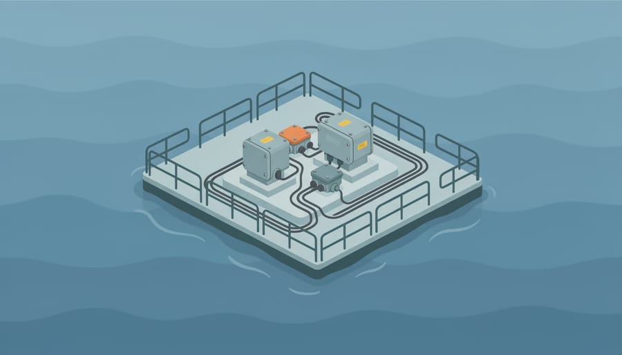
Isolation Monitoring and Ground Fault Detection
Maintaining electrical safety in floating PV systems requires specialized monitoring equipment that can detect faults before they become hazardous. Two technologies form the backbone of safety in electrically floating configurations: isolation monitoring devices (IMDs) and residual current devices (RCDs).
Isolation Monitoring Devices (IMDs)
An IMD continuously measures the insulation resistance between the DC circuit and earth ground. In an electrically floating system, this resistance should remain high, typically above 1 megohm for most installations. When moisture penetrates cable insulation or corrosion compromises a connection, the IMD detects the degradation before it creates a dangerous fault path.
These devices work by applying a small test voltage between the floating circuit and ground, then measuring the resulting current. Modern IMDs provide real-time resistance values and can trigger alarms or system shutdowns when insulation resistance drops below safe thresholds. For floating PV installations, this early warning capability is essential because water accelerates fault progression once insulation is compromised.
Residual Current Devices (RCDs)
While IMDs monitor DC circuits, RCDs protect AC circuits by detecting current imbalances between phase and neutral conductors. When current “leaks” through an unintended path, such as through water or a person touching energized equipment, the RCD opens the circuit within milliseconds.
For floating solar installations, Type B RCDs are typically required because they can detect both AC and DC residual currents, including smooth DC currents produced by modern inverters. Standard Type A or AC RCDs may not respond appropriately to DC faults, leaving dangerous conditions undetected.
Integrated Safety Approach
Effective protection combines both technologies. IMDs provide continuous monitoring of the floating DC array’s isolation integrity, while RCDs offer immediate disconnection when AC-side faults occur. This layered approach ensures comprehensive coverage across the entire electrical system, from panels through inverters to grid connection.
Equipotential Bonding in Water-Based Installations
In an electrically floating array, you must still bond all conductive parts together at the same potential, even though the entire system remains isolated from earth ground. This equipotential bonding creates a local reference plane that prevents dangerous voltage differences between touchable metal surfaces while maintaining the floating status. Without proper bonding, a fault in one part of the installation could create a lethal voltage between the array frame and an inverter enclosure, endangering maintenance personnel.
The bonding network connects all exposed conductive parts within the floating installation:
- PV mounting frames and structural supports
- Inverter and combiner box enclosures
- Metal walkways and access platforms
- Mooring systems and anchoring hardware
Use corrosion-resistant bonding conductors sized according to fault current calculations, typically copper or tinned copper with marine-grade terminations. Every connection point must maintain low resistance despite constant moisture exposure, which requires stainless steel hardware and anti-corrosion compounds rated for marine environments.
The bonding conductor runs throughout the floating platform, connecting to each array frame and equipment enclosure at multiple points to create redundant paths. This design ensures that even if one connection corrodes, the equipotential plane remains intact. In system design engineering treating the entire floating structure as a unified conductive body prevents dangerous potential differences while preserving isolation from the water itself.
Test bonding continuity during commissioning and at regular intervals, measuring resistance between distant points on the platform. Readings above design thresholds indicate corrosion or failed connections that compromise personnel safety, requiring immediate remediation before the system can safely return to operation.
Design Considerations for Electrically Floating Configurations
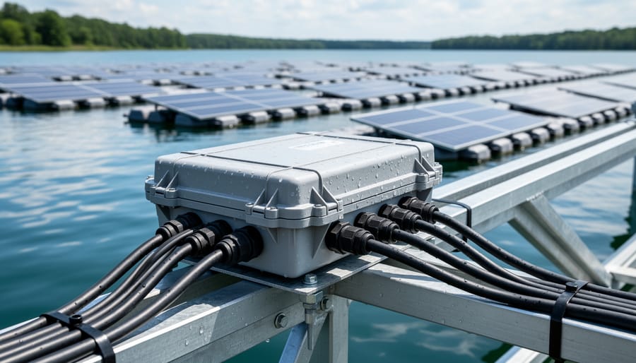
Inverter Selection and Configuration
Inverter selection becomes crucial for maintaining electrical isolation in floating PV systems. The fundamental choice between transformerless and transformer-based inverters directly impacts safety and system configuration.
Transformerless inverters, while lighter and more efficient, require galvanic isolation between the DC and AC sides to maintain electrical floating status. Most modern transformerless models achieve this through sophisticated electronic isolation, but engineers must verify the manufacturer’s specifications confirm true galvanic isolation. Without it, the PV array cannot remain electrically isolated from the AC grid ground.
Transformer-based inverters inherently provide galvanic isolation through their internal transformer, automatically separating DC and AC circuits. This makes them the simpler, more reliable choice for floating installations where maintaining electrical isolation is non-negotiable. The trade-off comes in added weight, cost, and slightly reduced efficiency compared to transformerless alternatives.
Configuration requirements extend beyond the inverter itself. The inverter must integrate with isolation monitoring devices that continuously verify the DC array’s floating status. When isolation resistance drops below safe thresholds, typically 1 MΩ or higher depending on system voltage, the monitoring system should trigger an alarm or shutdown.
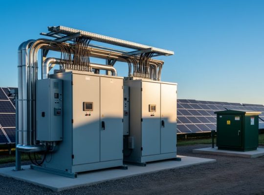
For floating installations, inverters also need enhanced protection ratings. IP65 or higher ingress protection shields internal components from the humid environment, though the inverter housing itself typically sits on the floating platform rather than directly exposed to spray. Proper ventilation remains essential despite water proximity, as inverters generate significant heat during operation.
String inverter configurations allow isolated monitoring of individual array sections, making fault location easier in the distributed layout common to floating platforms.
Cable Routing and Insulation Integrity
Cable insulation integrity determines whether an electrically floating array stays floating or develops dangerous paths to ground. Water constantly tests every weak point in your cabling system through humidity, spray, and direct contact during maintenance or storms.
Choose cables rated for wet locations with double insulation as the baseline. UV-resistant outer jackets prevent degradation from reflected sunlight off water surfaces, which can be 30% more intense than land-based exposure. Marine-grade cable glands and sealed entry points stop moisture creeping into conduit runs where it accelerates insulation breakdown.
Route cables to minimize water pooling zones. Elevated pathways between pontoons beat submerged crossings, but when underwater runs are unavoidable, use armored cable with continuous monitoring of insulation resistance. Drip loops before junction boxes prevent water traveling along cable surfaces into electrical connections.
Test insulation resistance quarterly using a megohmmeter, targeting values above 100 MΩ for low-voltage DC circuits. Declining resistance trends signal moisture ingress before it causes failures. Float switches in junction boxes alert you to water intrusion that could create unintended ground paths.
Cable ties and clips must be non-metallic to avoid creating tiny galvanic cells between dissimilar metals in the humid environment. Even small corrosion spots eventually pierce protective jackets, compromising the isolation that keeps your array electrically floating.
Monitoring and Maintenance Protocols
Electrically floating systems demand rigorous monitoring to catch isolation degradation before it becomes a safety hazard. Install isolation monitoring devices that continuously measure resistance between the floating array and water, triggering alarms when readings drop below safe thresholds (typically 50 kΩ per volt of system voltage). Schedule monthly visual inspections of all cable entry points, junction boxes, and connectors for moisture ingress, water infiltration is the most common cause of isolation failure. Use thermal imaging quarterly to identify hot spots that may indicate developing insulation breakdown or corrosion at connection points.
Maintenance protocols should include annual megohmmeter testing of all circuits to verify insulation resistance meets manufacturer specifications, performed during dry conditions when possible. Document all readings to track degradation trends over time. Pay particular attention to underwater cable sections and floating platform connections, where movement and moisture exposure accelerate wear. Any reading below manufacturer minimums requires immediate investigation and repair before re-energizing the system.
Keep detailed logs of all monitoring data and maintenance activities, regulators increasingly require proof of ongoing diligence for water-based installations. The same attention to detail that goes into initial support design must extend throughout the system’s operational life to maintain electrical isolation and protect both personnel and equipment.
Common Challenges and Solutions
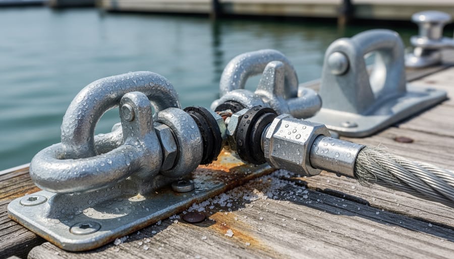
Corrosion and Degradation Effects
Floating PV systems face constant exposure to water, humidity, and temperature fluctuations that gradually compromise electrical isolation. Saltwater environments prove particularly aggressive, with spray and moisture accelerating corrosion of metallic components including junction boxes, cable glands, and bonding connections. Even freshwater installations aren’t immune, dissolved minerals and organic matter create conductive pathways that erode insulation resistance over time.
Corrosion typically starts at connection points where dissimilar metals meet or where protective coatings have minor imperfections. As corrosion progresses, it creates unintended ground paths that defeat the electrically floating configuration, potentially exposing personnel to shock hazards and triggering false fault alerts. UV degradation compounds the problem by breaking down cable jackets and enclosure seals, allowing moisture ingress that further reduces isolation.
Prevention requires specifying marine-grade components from the outset. Stainless steel fasteners, sealed junction boxes rated IP67 or higher, and cables with double-layer insulation designed for wet environments form the foundation. Apply conformal coatings to PCBs within monitoring equipment, and use corrosion inhibitors at all metallic junctions. Regular inspection protocols should verify torque on bonding connections and check for visible corrosion or insulation damage.
Integration with proper electric substation design ensures that monitoring systems can detect degradation before it compromises safety. Schedule annual insulation resistance testing across all circuits, tracking trends rather than waiting for absolute failures. Replace compromised components proactively, corrosion never reverses, only accelerates.
Fault Detection in High-Humidity Environments
High humidity and water exposure in floating PV environments complicate fault detection in ways that land-based systems never encounter. Moisture on connector surfaces, condensation inside junction boxes, and intermittent contact between components can trigger nuisance trips in isolation monitoring devices. An IMD might register a fault when morning dew creates a temporary low-resistance path, only to clear once the sun evaporates the moisture. Without context, maintenance teams waste time chasing phantom faults instead of addressing real electrical issues.
More dangerously, persistent high humidity can mask genuine insulation failures. If an entire array experiences uniformly degraded insulation due to moisture ingress across multiple strings, the IMD may fail to detect the gradual decline because it measures relative changes rather than absolute insulation values. A string with compromised cable insulation might show only marginally worse readings than its neighbors, staying below alarm thresholds even as the entire system approaches unsafe conditions.
Effective fault detection in these environments requires multiple validation layers. Combine IMDs with regular manual insulation resistance testing using a megohmmeter during dry conditions to establish baseline values. Track trends over time rather than relying solely on threshold alarms. Install humidity sensors inside critical enclosures to correlate apparent faults with environmental conditions. When an IMD trips, verify whether ambient humidity or actual insulation failure caused the event before dispatching repair crews.
Design junction boxes and cable entries with superior ingress protection ratings beyond standard IP65. Even small amounts of condensation inside enclosures create enough conductivity to confuse sensitive monitoring equipment and obscure real electrical hazards.
Educational Resources and Professional Development
Understanding the electrical complexities of floating PV systems requires specialized education that bridges theoretical knowledge with practical application. Mose Solar addresses this need through collaborative educational programs developed in partnership with leading universities, offering aspiring photovoltaic professionals structured pathways to master advanced topics like electrical isolation and safety protocols.
These university-developed programs combine fundamental electrical theory with hands-on training in floating solar-specific challenges. Curriculum modules cover isolation monitoring device selection, equipotential bonding techniques for water-based installations, and troubleshooting procedures for maintaining electrical floating status throughout system lifecycles. Students gain exposure to real case studies where improper electrical isolation led to safety incidents, learning to identify and prevent similar failures in their future projects.
For professionals seeking industry-recognized credentials, several certification bodies now offer specialized floating PV qualifications. The North American Board of Certified Energy Practitioners (NABCEP) includes floating solar considerations in their advanced PV installation specialist certification, while European organizations like TÜV offer dedicated floating PV structural and electrical system design courses that emphasize electrical safety protocols.
Practical training opportunities extend beyond classroom learning. Mose Solar facilitates access to pilot installations where students can observe operational floating PV installation best practices, including live demonstrations of isolation monitoring systems and fault detection procedures. These experiences prove invaluable when transitioning from theoretical understanding to field implementation.
Ongoing professional development remains critical as technology evolves. Webinar series, technical workshops, and peer-reviewed research publications keep practitioners current on emerging isolation techniques, updated safety standards, and innovations in floating PV electrical system design that enhance both safety and performance in water-based installations.
Proper electrical floating implementation stands as a non-negotiable foundation for safe, reliable floating PV installations. The unique challenges water bodies present, conductive environments, corrosion risks, moisture exposure, demand electrical configurations that traditional ground-mounted systems never encounter. Cutting corners on isolation monitoring, equipotential bonding, or inverter selection creates hazards that can compromise both personnel safety and system longevity.
As floating solar capacity expands globally, driven by land constraints and reservoir optimization opportunities, the industry needs professionals who understand these technical nuances. The stakes extend beyond individual projects: poorly implemented systems erode public confidence and invite regulatory scrutiny that affects the entire sector.
For those entering this field, comprehensive education makes the difference between superficial familiarity and genuine expertise. Mose Solar’s educational programs, developed in collaboration with universities, provide structured pathways to master floating PV structural and electrical system design principles. These programs address practical implementation challenges alongside theoretical foundations, preparing students for real-world project demands.
The floating solar market will continue evolving, presenting new configurations, larger installations, and hybrid applications that combine energy generation with aquaculture or water management. Professionals who invest in proper training today position themselves to lead tomorrow’s innovations while maintaining the safety standards that protect workers, equipment, and the technology’s reputation.
Whether you’re an aspiring engineer, installer, or project manager, seek rigorous education before claiming expertise. The water won’t forgive electrical shortcuts.