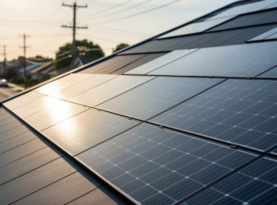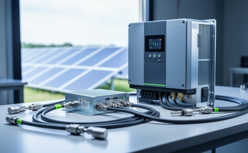
A z-source inverter is a single-stage power conversion device that incorporates a unique impedance network between the DC source and the inverter bridge, enabling voltage buck-boost capability without requiring an additional DC-DC converter. This topology fundamentally changes how inverters handle voltage mismatches and system faults, making it particularly valuable in photovoltaic applications where panel output voltage fluctuates with irradiance and temperature.
Unlike traditional voltage-source inverters that can only step down DC voltage or current-source inverters that require bulky input inductors, the z-source configuration uses a crossed LC impedance network to create a shoot-through state. This allows the inverter to boost input voltage during operation while maintaining the same switching devices and control architecture. The result is a more compact, efficient system that eliminates the cascaded conversion stages common in conventional solar inverter designs.
The technology addresses a persistent challenge in renewable energy systems: managing wide input voltage ranges without sacrificing conversion efficiency or requiring oversized components. For solar installations operating under partial shading, temperature swings, or intentional power curtailment, z-source inverters maintain stable AC output even when panel voltage drops significantly below nominal levels. This operational flexibility has attracted attention from system integrators working on distributed generation projects and microgrid applications where resilience matters as much as efficiency.
This article examines the technical principles that distinguish z-source inverters from conventional topologies, explains the impedance network configurations available, and explores their practical deployment in modern photovoltaic systems. Engineering students and industry professionals will find detailed operational insights grounded in real-world application scenarios.
What a Z-Source Inverter Means for Solar PV Systems
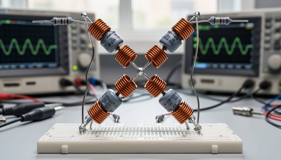
A z-source inverter is a power electronic converter that incorporates a unique impedance network between the DC source and the inverter bridge, enabling it to perform voltage step-up (boost) and step-down (buck) functions within a single conversion stage. Unlike conventional photovoltaic inverters that require separate DC-DC converters to handle varying solar panel voltages, a z-source design achieves this flexibility through a passive network of inductors and capacitors arranged in a distinctive X-shaped configuration.
This topology fundamentally differs from traditional inverter designs. Voltage-source inverters, the most common type in solar applications, can only step down voltage and require strictly regulated DC input. They cannot tolerate both switches in the same inverter leg conducting simultaneously, a condition called shoot-through that would destroy a conventional inverter. Current-source inverters avoid this vulnerability but introduce their own limitations, including the need for large inductors and inability to handle open-circuit conditions.
The z-source inverter breaks these constraints. Its impedance network not only tolerates shoot-through states but actively uses them as an operational mode to regulate voltage. This allows the inverter to accept a wide range of DC input voltages directly from solar arrays without additional conversion hardware, particularly valuable for installations with shading, temperature fluctuations, or modular configurations like solar tiles where string voltages vary significantly.
- Impedance Network
- A passive circuit of inductors and capacitors in an X-configuration that couples the DC source to the inverter bridge, enabling bidirectional power flow and voltage regulation.
- Shoot-Through State
- An operating mode where both switches in the same inverter leg conduct simultaneously, which is forbidden in conventional inverters but deliberately utilized in z-source designs for voltage control.
- Buck-Boost Capability
- The ability to both increase and decrease voltage in a single stage, eliminating the need for separate DC-DC conversion hardware in solar systems with variable input.
- Voltage-Source Inverter
- A traditional inverter topology requiring a stable DC voltage input and separate boost circuitry, which cannot tolerate shoot-through conditions without catastrophic failure.
- Quasi-Z-Source
- An improved variant of the original z-source topology offering continuous input current and reduced stress on passive components, making it particularly suitable for photovoltaic applications.
This paradigm shift means photovoltaic systems can achieve greater energy harvest from panels operating at non-optimal voltages, simplify system architecture by eliminating conversion stages, and improve reliability through reduced component count. For solar installations facing real-world conditions, partial shading, aging modules, or temperature extremes, z-source technology offers a more resilient approach to power conversion than conventional designs.
How Z-Source Inverters Work
The Impedance Network Architecture
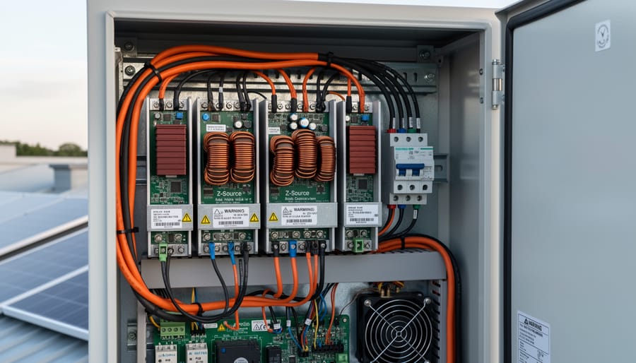
The heart of a z-source inverter is its unique impedance network, sometimes called an LC impedance network or Z-network. This passive circuit sits between the DC input (such as a photovoltaic array) and the inverter bridge, distinguishing the topology from conventional designs that connect the source directly to switching components.
The network comprises two inductors (L₁ and L₂) and two capacitors (C₁ and C₂) arranged in what engineers often describe as an X-shaped or lattice configuration. One inductor connects in series with the positive rail, while the other connects in series with the negative rail. The capacitors bridge across these rails in a diagonal arrangement, creating the characteristic cross-coupled topology. This symmetrical layout forms what amounts to a two-port network with specific impedance characteristics that give the topology its name.
Unlike a simple LC filter, this arrangement creates a controlled impedance path that can store and release energy dynamically. When the inverter bridge enters certain switching states, the network’s inductors accumulate magnetic energy while the capacitors provide voltage support. During other states, stored energy releases back into the circuit, enabling voltage transformation without rotating machinery or additional active components.
The bidirectional nature emerges from the network’s passive structure. Energy can flow from the DC source through the impedance network to the inverter bridge and ultimately to the AC load. Equally, the same network topology allows reverse power flow when needed, making it suitable for applications with battery storage or regenerative loads.
This passive configuration provides inherent voltage regulation because the capacitors maintain relatively stable voltages while the inductors smooth current ripple. The network naturally filters high-frequency switching harmonics, reducing electromagnetic interference compared to direct-coupled inverter bridges. Component values determine the impedance characteristics and therefore the voltage boost ratio achievable during shoot-through operation.
Shoot-Through States and PWM Control
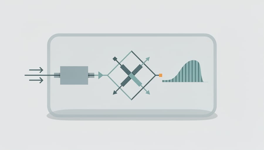
In conventional voltage-source inverters, the bridge switches can never be on simultaneously, such a condition creates a short circuit that destroys the device. Z-source inverters break this rule by design. They introduce a shoot-through state, where both upper and lower switches in the same inverter leg conduct at the same time, storing energy in the impedance network rather than shorting the DC bus. This simple yet revolutionary change eliminates the need for the dead time that plagues traditional inverters and unlocks the buck-boost capability that makes z-source topologies so compelling for solar applications.
Shoot-through states are carefully controlled insertion periods within the pulse-width modulation (PWM) switching cycle. During normal operation, the inverter switches just as a traditional design would, generating AC output through standard six-step or space-vector modulation. Then, at precise intervals determined by the control algorithm, the controller triggers a shoot-through condition, both switches close, the impedance network sees a short on its output side, and current flows into the inductors while capacitors discharge. This energy storage phase lasts microseconds, typically 10-30% of the switching period depending on the desired voltage boost ratio.
The duty cycle of these shoot-through periods directly sets the voltage gain. Increase the shoot-through duration and the inverter delivers higher AC voltage from the same DC input; reduce it and the inverter steps down voltage instead. This control is continuous and dynamic, the PWM controller adjusts shoot-through duty in real time as panel voltage fluctuates with cloud cover or temperature swings, maintaining stable grid output without a separate DC-DC converter.
Several PWM strategies manage shoot-through insertion. Simple constant boost control maintains a fixed shoot-through duty regardless of operating conditions, while maximum boost control maximizes voltage gain within safe component limits. Advanced algorithms distribute shoot-through periods symmetrically across all three phases in three-phase systems, minimizing output current ripple and balancing inductor stress. The controller must coordinate shoot-through timing with the fundamental AC waveform synthesis, inserting energy storage pulses during zero-voltage vectors or distributing them across active switching states depending on the modulation scheme.
This approach solves two problems at once. Traditional inverters require 200-500 nanosecond dead times between upper and lower switch transitions to prevent shoot-through faults, creating voltage distortion and limiting efficiency. Z-source designs deliberately exploit shoot-through, so switches can transition instantly with no protective delay. Meanwhile, the voltage boost happens inherently during these same intervals, collapsing what would otherwise require a boost converter, its controller, and an additional set of magnetics into the inverter stage itself.
Voltage Boost and Buck Capabilities
The z-source network’s bidirectional power flow capability enables simultaneous voltage boost and buck operation within a single conversion stage. During shoot-through periods, the impedance network stores energy in its inductors and capacitors, creating a boosted DC-link voltage that exceeds the input voltage from the photovoltaic array. When the inverter operates in traditional switching states, the same network can step down voltage when necessary. This dual functionality proves particularly valuable in solar installations where panel voltage fluctuates with irradiance and temperature, morning low-light conditions might require significant voltage boost, while peak midday generation may need only minimal adjustment or even voltage reduction.
By integrating both functions into the impedance network, z-source inverters eliminate the separate DC-DC converter stage that traditional photovoltaic systems require for maximum power point tracking across wide voltage ranges. This consolidation reduces component count, improves overall efficiency by minimizing conversion losses, and simplifies system design for installations using emerging technologies like solar tiles where string voltages vary significantly throughout the day.
Z-Source Inverter Configurations and Variants
Traditional Z-Source Topology
The traditional Z-source topology features a symmetric impedance network formed by two inductors (L₁ and L₂) and two capacitors (C₁ and C₂) arranged in an X-shaped configuration between the DC source and the inverter bridge. The inductors and capacitors are typically identical in value, creating a balanced network that stores and transfers energy during shoot-through and non-shoot-through states. This original design introduced the revolutionary concept of allowing brief short-circuit conditions across the inverter bridge legs, previously forbidden in conventional inverters, to boost the DC-link voltage. While elegant in its symmetry, the traditional topology presents some practical limitations: it draws discontinuous current from the DC source, creating potential electromagnetic interference issues in photovoltaic applications, and places relatively high voltage stress on the capacitors during shoot-through periods, requiring robust component selection and thermal management.
Quasi-Z-Source Networks
The quasi-Z-source (qZS) network emerged as a refinement that addresses several practical limitations of the traditional topology. Its distinguishing feature is a reconfigured impedance network that shares a common ground between the DC source and inverter bridge, enabling continuous input current rather than the pulsating current characteristic of conventional Z-source designs.
This continuous current draw matters significantly for photovoltaic arrays. Solar panels perform optimally when connected to loads with smooth current profiles, as discontinuous current can interfere with maximum power point tracking algorithms and introduce additional electromagnetic interference. The qZS topology’s steady input current simplifies DC-side filtering requirements and improves compatibility with MPPT controllers.
Component stress reduction represents another practical advantage. The modified network arrangement distributes voltage and current stresses more evenly across capacitors and inductors, potentially extending component lifespan and allowing use of lower-rated (and less expensive) passive elements. Capacitor voltage stress, in particular, decreases compared to traditional Z-source configurations operating at equivalent boost ratios.
For grid-tied solar installations, the common-ground characteristic simplifies compliance with safety standards that mandate specific grounding configurations. This structural benefit, combined with the improved current quality presented to PV arrays, explains why quasi-Z-source networks have gained traction in commercial solar inverter designs where reliability and regulatory compliance are paramount.
Other Advanced Variants
Beyond the traditional and quasi-Z-source configurations, researchers have developed specialized variants targeting specific performance metrics. Trans-Z-source inverters use coupled magnetics instead of discrete inductors, reducing component count and overall system volume while maintaining voltage boost capability. Embedded Z-source topologies integrate the impedance network directly within the inverter bridge structure, achieving more compact designs particularly suitable for space-constrained installations. Switched-inductor Z-source networks employ switched-capacitor techniques to achieve higher voltage gain ratios without proportionally increasing passive component size, addressing applications where extreme input voltage variation occurs. Each variant represents engineering trade-offs between efficiency, component stress, cost, and footprint, allowing system designers to optimize for their specific solar application requirements rather than accepting a one-size-fits-all approach.
Three-Phase vs. Single-Phase Implementations
Single-phase z-source inverters typically serve residential solar applications where grid connection requires 120V or 240V AC output. These designs use a simpler H-bridge configuration with the impedance network, making them cost-effective for systems under 10 kW. The reduced component count and straightforward control algorithms suit rooftop installations where space and budget matter most.
Three-phase implementations target commercial buildings and utility-scale plants requiring 480V or higher output. These use six-switch bridge topologies with the Z-source network, enabling balanced power delivery across three phases, critical for industrial loads and grid stability. Three-phase designs handle 50 kW to multi-megawatt ranges but require more sophisticated PWM control to coordinate shoot-through states across all three legs while maintaining phase balance. The added complexity pays off through higher power density and better harmonic performance at commercial scales.
How Z-Source Inverters Are Used in Solar PV Applications
Residential and Distributed Solar Systems
Z-source inverters address critical challenges in residential rooftop installations, where varying panel orientations, partial shading, and temperature fluctuations create substantial voltage swings throughout the day. Unlike conventional inverters that require narrow input voltage windows, z-source topology adapts to wide voltage variations without sacrificing conversion efficiency, a particularly valuable feature when integrating solar tiles and shingles into complex roof geometries.
These building-integrated photovoltaic (BIPV) products often operate at lower voltages than standard panels and experience greater voltage variation due to their distributed nature across different roof sections. The z-source inverter’s simultaneous buck-boost capability eliminates the need for separate DC-DC converters that would otherwise add cost, complexity, and conversion losses to each roof zone. Homeowners benefit from simplified system architecture and improved energy harvest across diverse installation conditions.
Mose Solar’s solar tiles and shingles pair effectively with z-source inverter technology because both prioritize aesthetic integration without compromising performance. The inverter’s continuous input current characteristic reduces electromagnetic interference, important when power electronics sit close to living spaces, while its shoot-through immunity provides robustness against installation errors. Combined with proven PV optimization methods z-source inverters help residential systems achieve higher overall yields despite the inherent variability in distributed solar arrays.
Grid Integration and Voltage Regulation
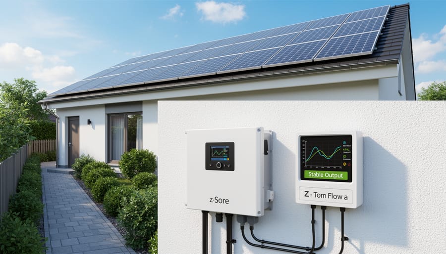
Z-source inverters excel at grid integration because their unique voltage boost/buck capability addresses one of solar PV’s most persistent challenges: maintaining stable output despite fluctuating input from panels and dynamic grid conditions. Modern grid codes, IEEE 1547 in North America, VDE-AR-N 4105 in Germany, and similar standards worldwide, demand that renewable energy systems remain connected during grid voltage disturbances rather than immediately disconnecting. Z-source topology inherently supports this voltage ride-through requirement.
When grid voltage sags occur, the inverter can increase its shoot-through duty cycle to boost output voltage and maintain synchronization. Conversely, during overvoltage events, it reduces boost action to prevent excessive power injection. This dynamic range happens within the same conversion stage, responding faster than systems requiring coordination between separate DC-DC and DC-AC stages.
The bidirectional impedance network also enables reactive power injection for grid support. Utilities increasingly require distributed generators to provide voltage regulation services during both normal operation and disturbances. Z-source inverters can supply or absorb reactive power while simultaneously managing real power transfer, supporting local voltage stability without additional hardware.
For installations using solar tiles or other building-integrated photovoltaics where partial shading creates voltage variations, this adaptability proves particularly valuable. The inverter compensates for input swings while delivering grid-compliant output, maintaining continuous operation across conditions that might force conventional inverters offline.
Energy Storage and Microgrid Systems
Z-source inverters excel in battery-coupled photovoltaic systems because their impedance network naturally handles the wide voltage swings inherent in energy storage applications. As batteries charge and discharge, terminal voltage can vary by 30% or more, a range that would require multiple conversion stages in traditional inverter designs. The z-source topology accommodates this variation within a single power conversion stage, improving round-trip efficiency and reducing component count.
In standalone microgrids, the bidirectional power flow capability becomes particularly valuable. The same z-source inverter can convert DC power from solar panels to AC for local loads, then reverse direction to charge batteries from surplus generation, and later invert stored battery power back to AC during periods without sun. This operational flexibility eliminates the need for separate battery chargers and grid-forming inverters.
The shoot-through state provides an additional benefit in microgrid applications: enhanced fault tolerance. When short-circuit conditions occur on the AC side, the z-source network can absorb fault current without immediate component failure, giving protection systems time to isolate the problem. This robustness matters significantly in remote installations where service response times may be measured in days rather than hours.
Advantages Over Conventional Inverter Technologies
Z-source inverters deliver compelling benefits that address fundamental limitations of traditional voltage-source and current-source inverter designs, making them particularly valuable for solar PV applications where efficiency, reliability, and voltage flexibility are critical.
The most significant advantage is single-stage power conversion. Conventional photovoltaic systems typically require separate DC-DC boost converters followed by DC-AC inverters to handle voltage regulation and conversion. Z-source topology integrates both functions into one stage, eliminating the losses, complexity, and cost associated with cascaded conversion. This architectural simplification reduces the total number of active switching components by roughly 30-40% compared to two-stage alternatives, translating directly to lower material costs and improved overall system efficiency.
The impedance network fundamentally changes how the inverter handles fault conditions and operational constraints. Traditional voltage-source inverters are vulnerable to shoot-through faults, simultaneous conduction of upper and lower switches in the same leg, which can destroy power electronics within microseconds. Z-source designs actually utilize controlled shoot-through states as part of normal operation, providing inherent protection against accidental shoot-through events that would be catastrophic in conventional topologies. This eliminates the need for conservative dead-time intervals between switching transitions, allowing faster switching speeds and reduced harmonic distortion in the output waveform.
The operational advantages extend across multiple performance dimensions:
- Single-stage power conversion eliminates intermediate DC-DC converter losses and complexity
- Elimination of dead-time requirements enables faster switching and lower total harmonic distortion
- Inherent shoot-through protection prevents catastrophic failures from switch overlap
- Reduced component count lowers system cost, weight, and potential failure points
- Improved reliability through simplified circuit topology and passive impedance network
- Enhanced power quality with better voltage regulation and lower output harmonics
The wide input voltage operating range proves particularly advantageous for photovoltaic applications where irradiance varies throughout the day. Z-source inverters maintain stable AC output across a broader DC input range than conventional designs, accommodating the natural voltage fluctuations from solar arrays without derating or shutdown. This capability becomes especially valuable in partially shaded conditions or when working with emerging solar tile installations where series string voltages can vary significantly.
From a power quality perspective, the voltage boost capability allows z-source inverters to support grid voltage during sags and ride through temporary disturbances that would force conventional inverters offline. This grid support function aligns with increasingly stringent interconnection standards for distributed solar generation, helping installations maintain compliance without additional compensation equipment.
Design Considerations and Implementation Challenges
Implementing z-source inverters in photovoltaic installations requires careful attention to component selection, control system design, and thermal management. While the topology offers significant advantages, several technical challenges demand expertise for successful deployment.
Component selection represents the first critical decision. The impedance network’s inductors and capacitors must handle both continuous conduction and shoot-through states without excessive losses or voltage stress. Designers typically select capacitors rated 30-40% above calculated peak voltage to account for transients, while inductors require low equivalent series resistance (ESR) to minimize conduction losses. These components constitute 15-20% of total inverter cost, making trade-offs between performance and budget essential.
Control complexity exceeds conventional inverter designs. The pulse-width modulation strategy must coordinate shoot-through intervals with traditional switching sequences, requiring digital signal processors (DSPs) or field-programmable gate arrays (FPGAs) capable of nanosecond-precision timing. Engineers must implement robust overcurrent protection that distinguishes intentional shoot-through states from fault conditions, a nuanced requirement that can complicate solar energy management systems integration.
Thermal management presents unique challenges. Unlike traditional inverters with predictable heat dissipation patterns, z-source designs experience variable thermal stress as the system transitions between buck and boost modes. This demands sophisticated cooling solutions and derating strategies that account for worst-case operating conditions rather than average power throughput.
Electromagnetic interference (EMI) mitigation requires particular attention. The impedance network’s high-frequency current ripple can generate conducted and radiated emissions that exceed regulatory limits without proper filtering. Designers must allocate physical space and budget for input/output filters, shielding, and layout optimization.
For applications involving solar storage integration, bidirectional power flow introduces additional complexity. The control system must manage seamless transitions between grid-tie, battery charging, and islanded operation modes while maintaining voltage stability across the impedance network.
Testing and validation timelines typically extend 20-30% longer than conventional inverter projects, reflecting the need to verify shoot-through operation across all anticipated operating conditions and fault scenarios.
Current Research and Educational Opportunities
Z-source inverter technology remains an active area of academic investigation, with research groups worldwide pursuing improvements in efficiency, control algorithms, and specialized topologies. Universities are exploring advanced modulation techniques that minimize switching losses while maintaining voltage regulation across wider operating ranges. Recent work has focused on hybrid Z-source configurations that combine impedance networks with emerging wide-bandgap semiconductors like silicon carbide and gallium nitride, promising higher switching frequencies and reduced thermal management requirements.
Control strategy optimization represents another significant research frontier. Adaptive algorithms that dynamically adjust shoot-through duty ratios based on real-time input conditions can substantially improve conversion efficiency in photovoltaic applications where irradiance varies throughout the day. Some institutions are investigating predictive control methods that anticipate voltage transients and grid disturbances, enhancing the inverter’s ability to support grid stability during renewable energy integration.
Topology refinement continues as researchers develop variants with reduced passive component counts or improved power density. These modifications address practical deployment concerns like physical footprint and manufacturing cost, factors critical for commercial solar installations where space constraints and budget limitations influence design choices.
For aspiring photovoltaic professionals interested in mastering these advanced power electronics concepts, Mose Solar’s educational program provides structured learning pathways that connect theoretical knowledge with practical implementation. Our collaboration with universities ensures that curriculum content reflects current research directions and industry needs, preparing students for roles in renewable energy system design and optimization.
Academic partnerships also facilitate knowledge transfer between research environments and field applications, helping translate laboratory breakthroughs into commercially viable solar technologies. This bridge between academic innovation and industry deployment accelerates the adoption of improved z-source inverter designs in real-world photovoltaic installations.
Common Questions About Z-Source Inverters
Common Questions About Z-Source Inverters
Photovoltaic professionals evaluating z-source inverter technology for solar applications frequently raise questions about performance trade-offs, economic viability, and practical implementation constraints. Understanding these considerations helps determine when this advanced topology offers genuine advantages over established inverter architectures.
How does z-source inverter efficiency compare to traditional designs?
Z-source inverters typically achieve peak efficiencies of 94-97%, comparable to high-quality traditional inverters, though the single-stage conversion can reduce cumulative losses in systems that would otherwise require separate DC-DC conversion. The impedance network introduces some additional conduction losses, but eliminating a conversion stage often results in net efficiency gains for applications with wide input voltage variation.
Are z-source inverters cost-effective for residential solar installations?
Current pricing generally makes z-source technology more economical for commercial and utility-scale projects where the system-level benefits justify higher component costs. Residential applications using solar tiles or installations with significant shading may benefit from the voltage regulation capabilities, but conventional microinverters or string inverters with DC optimizers remain the standard choice for typical rooftop systems.
Do z-source inverters work with all photovoltaic module types?
Z-source inverters are compatible with monocrystalline PERC, multi-crystalline, thin-film, and other module technologies, with their wide input voltage range making them particularly suitable for mixed-string configurations or arrays with varying irradiance conditions. The bidirectional power capability also supports hybrid systems integrating different module types or battery storage.
What maintenance do z-source inverters require compared to traditional designs?
The passive impedance network has no moving parts or wear components, potentially offering reliability advantages, though the additional inductors and capacitors represent more components that could theoretically fail. Regular inspection of thermal management systems and electrical connections follows the same protocols as conventional inverters.
The primary adoption barrier for z-source technology remains limited commercial availability compared to mature inverter platforms. Most major manufacturers have not yet integrated z-source topologies into their standard product lines, with the technology appearing primarily in specialized applications and research installations. As academic institutions continue developing optimized control strategies and component sizing methods through programs like those Mose Solar supports, expect broader commercialization to follow once manufacturing economies of scale reduce the cost premium for the impedance network components.
Z-source inverters represent a meaningful step forward in photovoltaic power conversion, addressing voltage variability and conversion efficiency challenges that have long constrained solar system design. By eliminating the need for separate DC-DC conversion stages while maintaining buck-boost capabilities, this topology streamlines system architecture and reduces component count, particularly valuable in installations where panel voltages fluctuate widely throughout the day.
The technology has moved beyond theoretical interest. Quasi-Z-source variants now appear in commercial solar applications where continuous input current and reduced capacitor stress matter. Research teams at universities worldwide continue refining control algorithms, exploring new impedance network configurations, and testing integration with energy storage systems. These developments suggest z-source topologies will occupy a growing niche in distributed generation and microgrid applications rather than displacing conventional inverters entirely.
For aspiring photovoltaic professionals, understanding z-source inverters provides insight into how power electronics evolve to meet specific system requirements. The impedance network concept demonstrates that innovation often comes from rethinking fundamental circuit arrangements rather than simply adding complexity. Whether you’re designing residential installations with solar tiles, engineering utility-scale plants, or optimizing battery-coupled systems, familiarity with advanced topologies expands your technical toolkit.
Mose Solar’s educational program includes coursework on emerging inverter technologies, often developed through collaboration with university research groups exploring these systems. Staying current with developments like z-source topologies positions you to evaluate new solutions as the solar industry matures and application demands diversify.