Z racking refers to a bracket-style photovoltaic mounting component characterized by its distinctive Z-shaped cross-sectional profile, engineered to support solar panels in a horizontal or near-horizontal orientation on elevated structures such as flat commercial roofs, carports, and ground-mount arrays. Unlike tilted or zigzag array configurations, Z-brackets function as the primary structural interface between the module frame and the underlying support rail, distributing wind and snow loads while maintaining panel alignment across large installations.
This hardware approach has gained traction in commercial-scale deployments where roof loading constraints, architectural integration, or simplified installation workflows drive design decisions. Z-profile extrusions offer several advantages: they eliminate the need for penetrating roof membranes when paired with ballasted systems, reduce installation labor through standardized attachment points, and accommodate thermal expansion without compromising structural integrity. Compliance with standards such as UL 2703 and ASCE 7 wind-load certification remains non-negotiable, particularly in regions subject to severe weather.
Understanding Z racking requires distinguishing it from unrelated layout strategies. The term occasionally surfaces in reference to zigzag panel arrangements intended to maximize array density on constrained sites, but those configurations represent a separate planning methodology rather than a hardware category. True Z racking addresses the mechanical question of how panels attach and remain secure, not how they are spatially arranged.
For aspiring photovoltaic professionals and industry stakeholders, mastering Z-bracket specifications, load-transfer mechanics, and code-compliant installation practices forms a critical competency. Mose Solar’s collaboration with university engineering programs and targeted educational offerings provide the technical depth required to evaluate, specify, and deploy Z racking systems with confidence in diverse project contexts.
What Z Racking Means in Solar Mounting
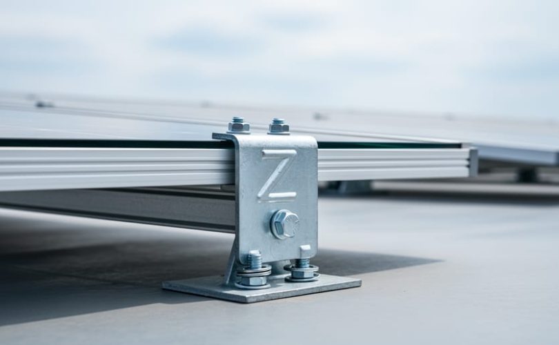
Z racking refers to a category of mounting hardware built around Z-shaped metal brackets or profiles that secure photovoltaic panels horizontally on elevated structures such as rooftops, carport canopies, and ground-mount frames. The name derives from the bracket’s distinctive cross-sectional profile, which resembles the letter Z when viewed from the side. This orthogonal shape creates two horizontal flanges, one for fastening to the underlying structural support and another for clamping the panel frame, connected by a vertical web that provides standoff distance and airflow clearance beneath the modules.
The Z bracket design emerged as a practical solution for commercial and industrial installations where horizontal panel orientation simplifies alignment, permits modular installation sequences, and accommodates architectural constraints. Panels mounted in this configuration can be placed in landscape or portrait mode depending on available dimensions and electrical stringing requirements. The horizontal approach contrasts with tilt-mount systems that angle panels toward the sun or tracker assemblies that follow solar azimuth throughout the day.
Confusion sometimes arises because the term “Z racking” can colloquially describe zigzag panel arrangements on flat roofs, where alternating rows are staggered to minimize shading and maximize array density. That usage refers to layout geometry, not hardware components. In the context of PV mounting standards and certification frameworks, Z racking denotes the physical bracket hardware that enables horizontal installation, irrespective of array pattern. Understanding this distinction matters for professionals specifying components, reviewing structural drawings, and ensuring compliance with load-bearing and electrical grounding criteria.
Manufacturers produce Z brackets in aluminum alloy and stainless steel formulations, with flange widths and web heights tailored to specific panel frame thicknesses and required standoff clearances. Certification testing evaluates these profiles under static and dynamic loads to verify they meet structural safety margins for wind uplift, snow accumulation, and seismic events.
How Z Racking Hardware Functions

Attachment to Structural Supports
Z brackets secure to structural supports through either penetrating or non-penetrating fastening methods, with the choice driven by substrate type, load requirements, and waterproofing concerns. Penetrating attachments use lag bolts, screws, or through-bolts drilled into rafters, purlins, or steel beams, creating direct mechanical connections that transfer wind uplift and gravity loads into the building structure. These fasteners typically require flashing and sealant systems to maintain roof membrane integrity. Non-penetrating options, common on flat commercial roofs with membrane systems, rely on ballasted supports, adhesive-backed pads, or clamp assemblies that attach to standing seam profiles without puncturing the weatherproofing layer.
Load transfer occurs through the bracket’s base plate or flange, which distributes concentrated panel and environmental forces across the attachment footprint. Proper spacing of fasteners along the Z bracket’s horizontal leg ensures uniform load distribution and prevents localized stress concentrations that could cause structural damage. Engineers calculate required fastener quantities and spacing based on wind zone classifications, dead loads from panels and snow, and safety factors prescribed by building codes. The bracket material, typically aluminum or stainless steel, must provide adequate strength while maintaining compatibility with dissimilar metals to prevent galvanic corrosion at fastener interfaces.
Panel Retention and Orientation
Panels attach to Z brackets through clamp assemblies that grip the module frame edges without compromising structural integrity or electrical bonding. Mid-clamps secure adjacent panel frames where they meet, while end-clamps fasten the outermost edges of the array. Each clamp typically includes a bolt that threads into the Z bracket’s mounting channel, allowing installers to adjust tension and achieve uniform contact pressure across the array.
Landscape orientation, where panel length extends horizontally, is most common on flat commercial roofs and carports, maximizing row width and simplifying wire management. Portrait orientation, with panels standing vertically, suits applications where bay dimensions or structural members dictate narrower spans. Installers maintain consistent spacing between rows by measuring from the Z bracket mounting points to the structural support centerlines, ensuring even weight distribution and clearance for thermal expansion.
Proper panel retention requires verifying that clamp threads engage fully, torque settings match manufacturer specifications, and no frame edges rest unsupported between brackets. This attention to detail prevents panel slippage under wind loads and maintains electrical grounding continuity throughout the array’s lifespan.
Applications and Installation Contexts
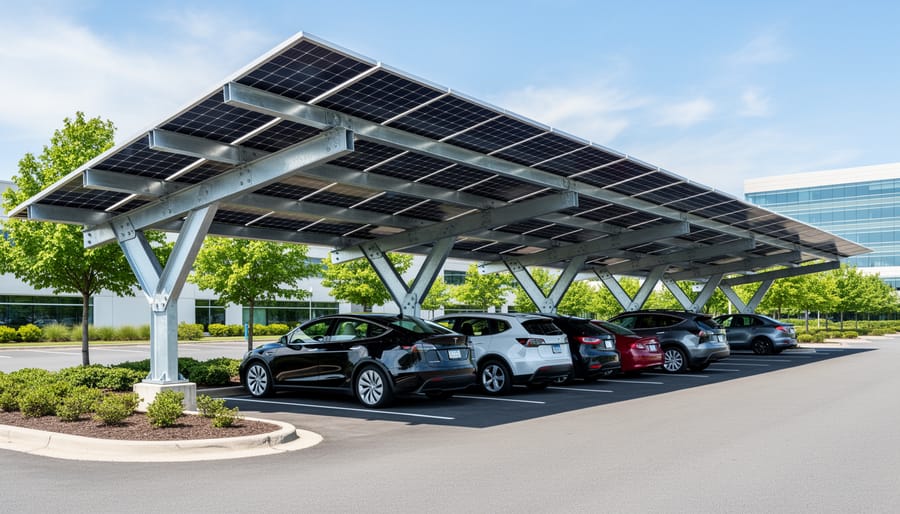
Z racking hardware finds its most practical applications in settings where panels must remain horizontal or where vertical space demands elevated mounting. Commercial flat roofs comprise the largest deployment category: low-slope membranes cannot support the concentrated loads of tilted frames, so Z brackets attach to structural purlins beneath the roof membrane, raising panels 6 to 12 inches above the surface. This configuration permits airflow underneath, cooling the panels and extending membrane life, while satisfying building code setback requirements and fire marshal access pathways.
Carport canopies represent another high-volume use case. Here, Z-shaped profiles bolt to steel or aluminum beams that form the canopy skeleton, positioning panels horizontally to create shade and weather protection for vehicles below. The bracket standoff distances accommodate electrical conduit runs and drainage slopes without penetrating the parking surface. Architectural integrations, such as building façade overhangs and transit shelter roofs, rely on Z racking to mount panels flush with design intent, often in coordination with BIPV standards that govern structural and aesthetic performance of building-integrated systems.
Ground-mount arrays occasionally employ Z brackets when site conditions prohibit traditional tilt-up racking, for instance, when local zoning caps array height or when the project demands a low visual profile near sensitive viewsheds. In these scenarios, horizontal mounting sacrifices some irradiance gain but simplifies foundation design and reduces wind loading.
- Commercial flat roofs: low-slope membrane systems with Z brackets fastened to underlying structural supports
- Carport canopies: elevated steel or aluminum frames requiring horizontal panel orientation for shade and weather protection
- Architectural integrations: façade overhangs, transit shelters, and building-attached structures where aesthetics and BIPV compliance dictate flush mounting
- Ground-mount arrays: sites with height restrictions or visual constraints that favor horizontal panel placement over tilted racking
Z racking contrasts sharply with tilt-mount systems that angle panels toward optimal sun exposure and with tracker systems that rotate to follow the sun’s arc. Tilt-mount racks deliver higher annual energy yield per panel but impose greater structural loads and require more vertical clearance. Trackers maximize output through dynamic orientation but add mechanical complexity, ongoing maintenance, and substantially higher installed cost. Z racking trades some generation capacity for installation simplicity, reduced structural demand, and suitability in constrained spaces, a deliberate design choice rather than a compromise. Aspiring PV professionals must evaluate site constraints, shading patterns, and economic modeling to determine whether the horizontal mounting approach justifies its yield penalty in a given application.
Certification Standards and Compliance Requirements
Structural and Safety Testing
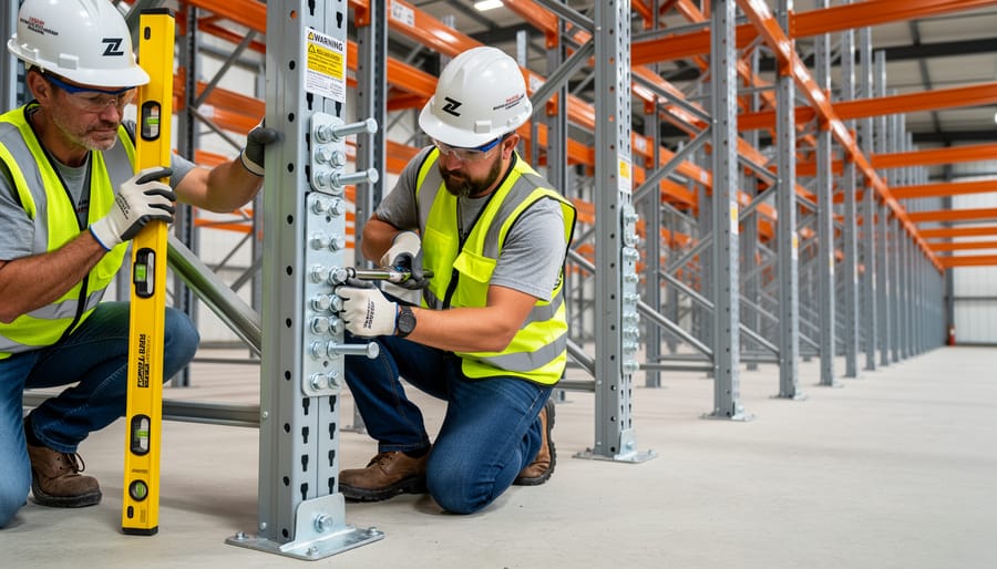
Structural and safety testing for Z racking systems evaluates whether horizontal mounting hardware can withstand real-world environmental forces without failure. Certification bodies require manufacturers to calculate design loads based on regional wind speed zones, snow accumulation patterns, and seismic activity levels defined in ASCE 7 standards. These calculations determine the maximum forces each Z bracket must support, typically expressed in pounds per square foot for wind uplift and downward snow pressure.
Static testing applies sustained loads to mounted panels over extended periods, verifying that Z brackets maintain structural integrity without permanent deformation. Engineers measure deflection at prescribed load levels and confirm connections remain secure. Dynamic testing subjects assemblies to cyclic forces simulating gusty winds and thermal expansion cycles, exposing potential fatigue points in bracket geometry or fastener joints.
Safety margins mandated by UL 2703 and similar frameworks require tested capacity to exceed calculated design loads by specified factors, commonly 1.5 to 2.0 times maximum expected forces. This cushion accounts for installation variations, material aging, and extreme weather events beyond typical design parameters. Testing protocols also assess fire resistance ratings and verify that bracket failure modes, if they occur, won’t create cascading structural collapse or electrical hazards. Proper grounding across all metallic components protects against lightning strikes and electrical faults, a concern extending beyond mounting hardware to inverter security and system-wide electrical safety. Documentation from accredited testing laboratories provides the compliance evidence required for permitting and installation approval.
Material Durability and Environmental Standards
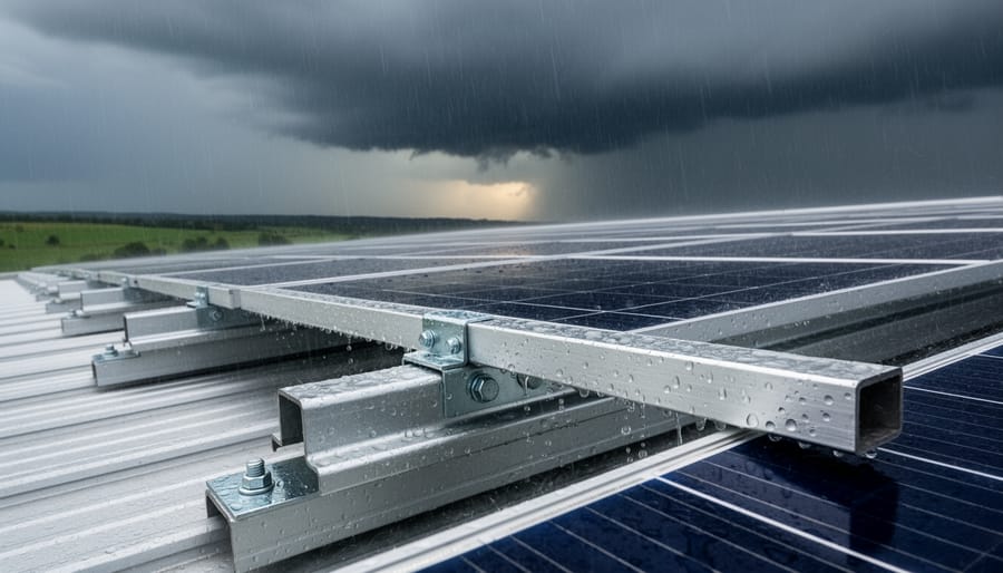
Z bracket materials must withstand decades of outdoor exposure across varied climatic zones. Aluminum alloys, typically 6000-series grades with anodized or powder-coated finishes, are evaluated for corrosion resistance through salt spray testing per ASTM B117, often requiring 1,000+ hours without significant degradation. Stainless steel hardware (304 or 316 grades) faces similar accelerated corrosion protocols to verify suitability in coastal or industrial environments where chloride or sulfur compounds accelerate oxidation.
UV stability testing subjects bracket coatings and polymeric components to simulated sunlight exposure equivalent to 20-30 years of real-world weathering. Standards such as ASTM G154 and ISO 4892 define test cycles that replicate UV intensity, moisture condensation, and thermal cycling. Degradation is measured by color shift, chalking, and loss of mechanical properties; passing thresholds ensure brackets maintain structural integrity and electrical bonding conductivity throughout the system’s rated lifespan.
Long-term performance criteria also include dimensional stability under freeze-thaw cycles (ASTM D6944) and resistance to biological growth in humid regions. Certification bodies require manufacturers to document material specifications, test results, and compliance with regional environmental standards, ensuring Z racking hardware performs reliably whether deployed in desert heat, alpine snow loads, or tropical humidity.
Electrical Grounding and Bonding
Proper electrical grounding and bonding in Z racking systems ensure personnel safety and equipment protection by establishing a continuous low-impedance path to earth. NEC Article 690 mandates that all exposed metal parts, panels, frames, Z brackets, rails, and structural supports, be effectively bonded and grounded. This typically involves grounding lugs or washers at each bracket-to-rail junction and bonding jumpers where painted or anodized surfaces interrupt conductivity. Many Z bracket designs incorporate pre-drilled grounding holes or serrated contact surfaces to simplify compliance. Installers must verify that the grounding electrode conductor is sized per NEC Table 250.66 and that all connections meet torque specifications. Systems also require module certifications confirming frame grounding compatibility, and some jurisdictions reference EMC certification to limit electromagnetic interference from improper bonding. Local amendments to the NEC or state electrical codes may impose additional testing or labeling requirements.
Design Considerations for PV Professionals
Selecting and specifying Z racking hardware demands careful evaluation of structural, electrical, and panel-specific parameters to ensure long-term performance and code compliance. Start by verifying that the bracket load capacity matches the dead load of the solar array plus anticipated live loads, wind uplift, snow accumulation, seismic forces, calculated per ASCE 7 for the project’s geographic location. Manufacturer datasheets provide maximum allowable loads for each bracket model, but confirm these values align with the engineered load report for the specific structure. Consult a licensed structural engineer early in the design phase to review roof or canopy framing capacity, fastener pull-out resistance, and any required structural reinforcement.
Bracket spacing intervals directly influence system stability and material costs. Typical Z bracket layouts place supports every 48 to 60 inches along the panel length, though high-wind zones or heavy snow regions may require tighter spacing. Verify that the chosen interval maintains panel flatness and prevents mid-span deflection that could stress laminate layers or frame corners. Cross-reference the panel manufacturer’s installation manual for maximum unsupported span limits, and coordinate these with the Z bracket manufacturer’s recommended spacing charts.
| Panel Size (mm) | Recommended Bracket Spacing (inches) | Wind Zone (ASCE 7) | Typical Roof Type |
|---|---|---|---|
| 1684 × 1002 | 48-54 | I, II | Flat commercial, low-slope TPO |
| 2108 × 1048 | 48-60 | I, II | Carport canopy, elevated structure |
| 2108 × 1048 | 42-48 | III, IV | Coastal or high-exposure roof |
| 2384 × 1303 (bifacial) | 36-48 | II, III | Ground-mount elevated frame |
Panel frame compatibility is another critical factor. Some Z brackets feature adjustable clamps that accommodate varying frame thicknesses (35mm to 50mm), while others are designed for specific profiles. Confirm that the bracket clamp geometry mates securely with the panel’s frame edges without causing stress concentrations or gaps. Mixing certified PV modules from different manufacturers on the same array may introduce frame dimension variability, so verify compatibility across all panel models before procurement.
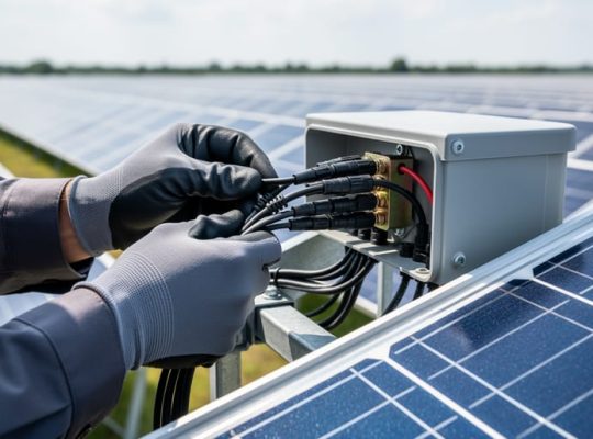
Integration with electrical balance-of-system components requires forethought. Plan wire management pathways that avoid kinking cables against sharp bracket edges, and ensure grounding hardware establishes continuous electrical bonding from each panel frame through the Z bracket to the main grounding conductor. Some bracket designs include factory-installed bonding lugs; others require field installation of separate grounding clips. Review the National Electrical Code (NEC) Article 690 requirements for system grounding and confirm the bracket material (aluminum or stainless steel) provides adequate conductivity or is bonded with listed grounding hardware.
Adhere strictly to manufacturer installation manuals. Torque specifications for fasteners, sealant application details, and assembly sequences are engineered to preserve warranty coverage and structural performance. Deviating from these instructions, using non-specified fastener grades, overtorquing clamps, or substituting sealants, can void certifications and create liability risks.
Common Questions About Z Racking Systems
Can Z racking hardware be installed on sloped roofs?
Yes, Z-shaped brackets can attach to sloped roofs, though they typically maintain horizontal panel orientation rather than following the roof pitch. Installers must account for the bracket height and ensure adequate standoff clearance for drainage and airflow beneath the panels.
How does horizontal mounting affect energy production compared to tilted arrays?
Horizontal installations generally produce less annual energy than optimally-tilted arrays because the panels receive sunlight at less favorable angles throughout the year. The performance gap varies by latitude and local climate, but horizontal mounting may be necessary for architectural constraints, permit requirements, or installations where roof pitch dictates orientation.
What warranty coverage applies to certified Z bracket systems?
Warranty terms vary by manufacturer, but most certified Z racking hardware carries 10 to 25-year product warranties covering material defects and structural integrity. Installation workmanship warranties are separate and typically provided by the contractor, not the hardware supplier.
Are there regional code variations that affect Z racking installations?
Yes, local building codes and authority having jurisdiction (AHJ) requirements can impose specific fastening methods, setback distances, fire ratings, and load calculations beyond baseline certification standards. Installers must verify compliance with state, county, and municipal codes before finalizing system design.
Beyond these core questions, installers often ask about compatibility between different panel frame types and Z bracket profiles. Most certified systems accommodate standard framed modules with 30 to 50 millimeter frame depths, but frameless or thin-film panels may require adapter hardware or alternative mounting solutions. Checking the manufacturer’s compatibility matrix before ordering hardware prevents field delays.
Another common concern involves long-term corrosion resistance in coastal or industrial environments. While aluminum and stainless steel brackets meet baseline durability standards, installations within three kilometers of saltwater or in areas with high sulfur dioxide concentrations benefit from upgraded alloys or protective coatings. Specifying marine-grade stainless steel or anodized aluminum adds initial cost but reduces maintenance requirements over the system’s 25-year lifespan.
Electrical inspectors frequently question bonding continuity in Z racking assemblies. The National Electrical Code requires a continuous grounding path from panels to the main service panel, which Z bracket systems achieve through metal-to-metal contact at clamp points or dedicated bonding jumpers. Third-party certification testing verifies that these electrical connections maintain integrity under thermal cycling and mechanical stress, but installers must follow torque specifications and bonding diagrams in the manufacturer’s installation manual to preserve that certified performance in the field.
Z racking, whether referring to Z-shaped bracket hardware for horizontal panel mounting on elevated structures or, less commonly, to zigzag ballasted configurations, represents a practical solution for diverse solar installation scenarios. For aspiring PV professionals, understanding the specific hardware approach defined in this guide (Z-shaped mounting brackets enabling landscape or portrait panel orientation) is essential for expanding deployment options across commercial rooftops, carport canopies, and architectural integrations where conventional tilt-mount systems may prove impractical.
Adherence to certification standards is non-negotiable. Properly tested Z bracket systems that meet structural load requirements, corrosion resistance benchmarks, and electrical grounding protocols ensure long-term safety, performance, and warranty compliance. Specifying certified hardware, following manufacturer installation guidelines, and collaborating with structural engineers to verify compliance with ASCE 7, UL 2703, and National Electrical Code requirements protects both project integrity and installer liability.
Mose Solar’s educational programs, developed in collaboration with university partners, equip aspiring professionals with the technical knowledge and practical skills needed to specify, install, and maintain compliant solar mounting systems confidently. From load calculation fundamentals to hands-on certification training, these programs prepare the next generation of PV specialists to navigate evolving standards, select appropriate hardware for each application context, and contribute to the safe, effective expansion of renewable energy infrastructure across residential, commercial, and utility-scale projects.