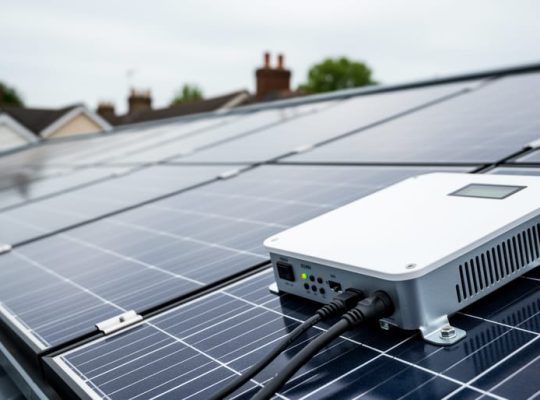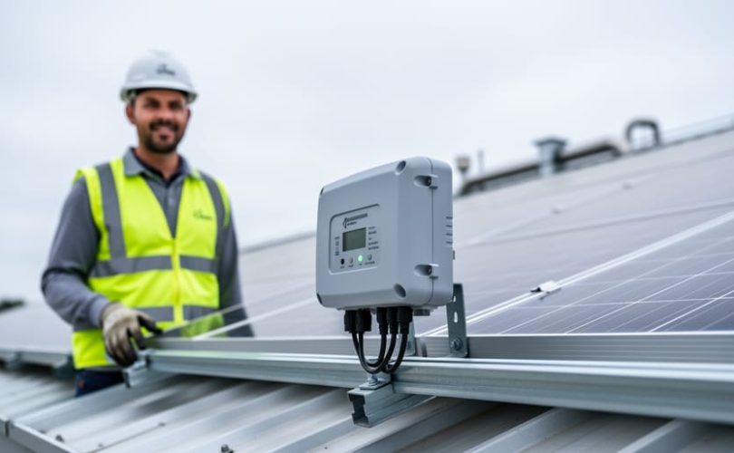
Optimizing module-level power electronics efficiency means improving the electrical conversion performance of power optimizers and microinverters attached to individual solar panels, typically yielding 1-3% additional energy harvest through proper configuration, firmware updates, and thermal management. The process requires a systematic approach to measurement, adjustment, and validation using specialized monitoring equipment and software tools, along with strict adherence to DC safety protocols when working with live photovoltaic systems.
Module-level power electronics have transformed solar installations by enabling panel-level monitoring and mitigation of shading losses, but their full potential depends on optimization that most installers overlook after commissioning. Unlike string inverters that operate at a single point on the power curve, MLPE devices create multiple maximum power point tracking opportunities, and each unit’s efficiency directly impacts overall system yield. A poorly configured power optimizer operating at 96% efficiency instead of 98.5% can cost a residential customer hundreds of dollars in lost production over the system’s lifetime.
The distinction matters particularly in 2026 as MLPE adoption continues to accelerate driven by code requirements for rapid shutdown and homeowner demand for granular monitoring. Mose Solar’s collaboration with leading universities has documented that typical field installations achieve 2-4% lower MLPE efficiency than laboratory ratings, a gap caused by suboptimal communication settings, inadequate ventilation design, and failure to update device firmware with manufacturer improvements. Through educational programs for installers and system designers, we’ve identified repeatable methods to close this performance gap.
This guide provides the technical framework aspiring PV professionals need to measure baseline MLPE efficiency, identify optimization opportunities, implement improvements safely, and verify results through quantitative measurement. The methodology applies equally to retrofit optimization of existing arrays and best-practice commissioning of new installations.
Understanding Efficiency Modules and Module-Level Power Electronics
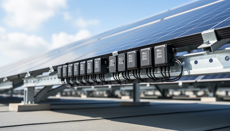
In module-level power electronics systems, efficiency modules are the power conversion devices that operate at the individual panel level to optimize DC power production and conversion. These components, primarily power optimizers and microinverters, function as distributed efficiency modules by performing maximum power point tracking (MPPT) and voltage conditioning for each solar panel independently, rather than relying on centralized string-level management.
Power optimizers serve as DC-to-DC converters attached to individual panels, continuously adjusting the electrical operating point to extract maximum power regardless of shading, soiling, or panel-to-panel performance variations. PV optimizers condition the DC voltage from each module before sending it to a central inverter, maintaining optimal voltage levels across the entire string even when individual panels experience different irradiance conditions. Microinverters perform both MPPT and DC-to-AC conversion at the module level, eliminating the need for a central inverter entirely by converting each panel’s output directly to grid-compatible alternating current.
The technical relationship between component efficiency and system performance extends beyond simple conversion losses. Each efficiency module introduces a small conversion loss, typically 1-3% depending on operating conditions, but simultaneously prevents much larger mismatch losses that occur when panels with different outputs are connected in series. A single shaded panel in a traditional string configuration can reduce the entire string’s output by 30-50%, whereas the same shaded panel in an MLPE system affects only its own production.
Component efficiency in MLPE devices varies with input voltage, power level, and operating temperature. Weighted efficiency, which accounts for real-world operating conditions rather than peak performance, provides a more accurate measure of how these modules contribute to total system energy yield across varying irradiance throughout the day.
Required Tools and Equipment for Efficiency Module Optimization
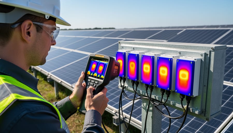
Optimizing efficiency modules in MLPE systems requires specific diagnostic and measurement tools that enable precise performance assessment and verification. While some basic instruments are commonly available, others are specialized pieces of equipment designed for photovoltaic system analysis. The right toolkit allows you to collect accurate baseline data, identify efficiency loss points, and validate improvements after optimization efforts.
- MLPE monitoring software (manufacturer-specific platforms like SolarEdge Monitoring Portal, Enphase Enlighten, or Tigo EI) for real-time performance tracking and historical data analysis
- True RMS digital multimeter with DC voltage and current measurement capabilities up to 1000V for verifying electrical parameters at module and optimizer level
- Pyranometer or reference cell irradiance sensor to measure solar irradiance (W/m²) and correlate power output with available solar resource
- Infrared thermal imaging camera (minimum 160×120 resolution) to detect hotspots, thermal derating, and cooling inefficiencies in MLPE components
- Clamp meter with DC measurement capability for non-invasive current monitoring without circuit interruption
- Data logging equipment or power analyzer to capture efficiency curves under varying irradiance and temperature conditions
- Portable weather station or temperature probe to record ambient and module temperature for thermal performance correlation
- Laptop or tablet with analytical software (Excel, MATLAB, or PVsyst) for processing performance data and calculating efficiency metrics
Not every optimization project requires the full complement of tools. Basic assessments can proceed with monitoring software and a quality multimeter, while comprehensive efficiency audits benefit from thermal imaging and precision irradiance measurement. Many professional installers invest in core diagnostic equipment first, then add specialized instruments as project complexity increases. Universities collaborating with Mose Solar often provide access to calibrated measurement equipment for students developing these assessment skills.
Technical Specifications and Performance Baselines

Before optimizing efficiency modules in MLPE systems, establish clear performance baselines through standardized metrics. These quantitative benchmarks allow you to measure improvement accurately and identify specific inefficiencies requiring attention.
Start by documenting weighted efficiency, which represents real-world performance across varying load conditions rather than peak values alone. CEC and weighted efficiency standards provide the industry-accepted framework, calculating performance at 10%, 20%, 30%, 50%, 75%, and 100% of rated capacity with specific weighting factors that reflect typical operating patterns.
Record CEC efficiency as your primary comparison metric. This single percentage figure, derived from the weighted calculation, enables direct comparisons between different MLPE components and serves as your optimization target. Most quality power optimizers and microinverters achieve CEC efficiency ratings between 95% and 98%, establishing realistic improvement expectations.
Maximum power point tracking accuracy determines how effectively your efficiency modules extract available power from each solar panel. Studies confirm MPPT accuracy as performance foundation, with tracking efficiency typically ranging from 98% to 99.5% under stable conditions. Document MPPT accuracy at various irradiance levels (200, 400, 600, 800, 1000 W/m²) because algorithm performance often degrades at lower light intensities.
Collect conversion efficiency curves across the full operating voltage and current range. These curves reveal efficiency drop-offs at the edges of the operating window and identify sweet spots where components perform optimally. Map efficiency against DC input voltage at 5-volt increments throughout the specified range.
Finally, establish thermal performance baselines by recording operating temperatures under different ambient conditions and load levels. Component efficiency typically decreases 0.3% to 0.5% for each 10°C rise above the rated temperature. Correlate efficiency measurements with case temperatures to quantify thermal derating effects affecting PV performance throughout daily and seasonal cycles.
Safety Protocols and System Shutdown Procedures
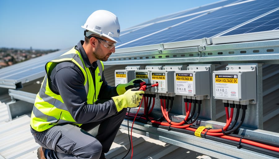
Working with module-level power electronics demands strict adherence to safety protocols because these systems operate at high DC voltages, often exceeding 600V, that pose severe electrocution and arc flash risks. Unlike AC systems that can be de-energized at a single disconnect point, MLPE components maintain voltage at the module level even when inverters are shut down, creating multiple potential hazard zones across the array.
Before any optimization work begins, verify that your system complies with NEC 690.12 rapid shutdown requirements, which mandate that conductors beyond one foot of the array must de-energize to 80V or less within 30 seconds of shutdown initiation. Test the rapid shutdown functionality using the emergency shutdown button or switch before proceeding with any hands-on work.
Essential personal protective equipment includes voltage-rated gloves (Class 0 minimum for systems up to 1000V), arc-rated clothing with appropriate ATPV ratings, safety glasses with side shields, and insulated tools rated for the system’s maximum voltage. Never rely on the monitoring interface alone to confirm de-energization, always use a properly rated multimeter to verify zero voltage at all connection points where you’ll be working.
Establish a clear shutdown sequence: activate rapid shutdown, verify voltage drop using metering equipment, lockout/tagout all disconnect points, and post warning signs at the array perimeter. If you encounter unexpected voltage readings, thermal anomalies detected by infrared cameras, or any signs of component damage during assessment, immediately halt work and consult a NABCEP-certified installer. Many optimization tasks, particularly those involving monitoring software and remote diagnostics, can be performed safely without physical contact with energized components, which should always be your first approach.
Step-by-Step Efficiency Optimization Process
Step 1: Baseline Performance Assessment
Begin by capturing a minimum of seven days of continuous monitoring data while the MLPE system operates under normal conditions. Use your monitoring platform to record DC-to-AC conversion efficiency at 15-minute intervals, logging input power from each module and output power from each optimizer or microinverter. Simultaneously measure irradiance levels with a calibrated pyranometer mounted in the same plane as the modules, and track module temperature using either embedded sensors or a handheld infrared thermometer at consistent measurement points.
Document efficiency performance across the full operating range: early morning and late afternoon low-irradiance periods (below 400 W/m²), midday peak production (800-1000 W/m²), and varying thermal conditions (module temperatures from 25°C to 65°C). Record voltage and current at both the DC input and AC output terminals using a true RMS multimeter to calculate instantaneous conversion efficiency. These baseline measurements establish your reference point for evaluating which optimization methods deliver measurable improvements and quantify the performance gap between current operation and manufacturer specifications.
Step 2: Identifying Efficiency Loss Points
Once you’ve collected baseline data, the next priority is identifying where efficiency losses occur within your MLPE system. Start by analyzing conversion efficiency patterns across different irradiance levels. Power optimizers and microinverters typically show reduced conversion efficiency at low light conditions (below 200 W/m²) and at peak loads. Plot your measured efficiency against input power to reveal these characteristic curves.
Thermal derating becomes evident when you compare performance data against ambient temperature records. If efficiency drops significantly when module temperatures exceed 45°C, inadequate heat dissipation is limiting performance. Thermal imaging data from your baseline assessment will show hot spots on optimizer housings or microinverter enclosures that correlate with these efficiency dips.
MPPT tracking errors appear as voltage operating points that drift from the theoretical maximum power point. Compare your recorded DC voltage against the expected MPP voltage calculated from module specifications and current irradiance. Deviations greater than 2-3 volts indicate suboptimal tracking algorithms or excessive voltage drop in DC cables.
Cable resistance losses reveal themselves through voltage differential measurements between module output terminals and optimizer inputs. Losses exceeding 1-2% of string voltage point to undersized conductors or poor connections. Similarly, examine AC-side voltage drops between microinverters and the junction box.
Mismatch conditions show up when individual module power outputs vary significantly despite similar irradiance exposure, forcing MPPT systems to compromise on optimal operating points.
Step 3: Configuration and Parameter Tuning
Modern MLPE systems provide software interfaces that allow direct configuration of efficiency-critical parameters. Accessing these controls requires authentication through the manufacturer’s platform, typically via web-based portals or dedicated applications connected to the system’s communication gateway.
Begin with MPPT algorithm settings. Most power optimizers offer multiple tracking modes, standard, fast response, and enhanced for low-light conditions. Select the mode matching your site’s typical operating environment. In installations with morning fog or frequent cloud transitions, fast-response MPPT reduces tracking delays that compound into measurable energy losses.
Next, optimize the voltage operating window. MLPE devices operate across a voltage range, but efficiency peaks in a narrower band. Review your baseline data to identify where modules actually operate, then configure the voltage setpoint to center this range. A 5-10V adjustment can shift operation into the highest-efficiency zone on the conversion curve.
Configure communication polling intervals to balance monitoring resolution with processing overhead. Excessive polling frequency forces the device to allocate power to communication rather than conversion. For most residential systems, 5-minute intervals provide adequate monitoring without efficiency penalties.
Finally, adjust thermal management thresholds if your climate data shows consistent temperature extremes. Some systems allow modified derating curves that maintain higher output before initiating thermal protection.
Step 4: Physical and Environmental Optimization
After addressing software-level parameters, turn your attention to the physical installation environment where efficiency modules operate. Real-world conditions, heat buildup, airflow restriction, shading, and cable placement, directly impact conversion efficiency and long-term performance.
Start with thermal management. Ensure adequate clearance around power optimizers and microinverters for passive convection. Remove any accumulated debris, leaves, or nesting material blocking ventilation channels. In rack-mounted installations, verify minimum spacing specifications between units; crowding reduces airflow and accelerates thermal derating. For roof-mounted systems in hot climates, consider reflective surfaces beneath equipment or additional standoff height to promote air circulation.
Address partial shading systematically. Even brief shadows from vent pipes, chimneys, or nearby structures disrupt MPPT algorithms and reduce efficiency. Relocate affected modules when feasible, or adjust optimizer groupings so shaded units don’t drag down unshaded neighbors. Document shading patterns across different seasons to anticipate performance variations.
Minimize resistive losses through proper cable routing. Use the shortest practical DC cable runs between modules and efficiency modules, avoiding coiled excess length that increases resistance and generates heat. Verify all connections are torqued to manufacturer specifications, loose terminals create hot spots and voltage drop. Check grounding integrity with a low-resistance ohmmeter; poor grounding introduces electrical noise that degrades MPPT accuracy and creates safety hazards.
Step 5: Firmware Updates and Advanced Features
Manufacturer firmware updates frequently deliver measurable efficiency improvements without hardware modifications. Before proceeding, verify your MLPE system’s current firmware version through the monitoring platform’s device management interface and cross-reference it against the manufacturer’s latest release. Download updates only from official manufacturer portals, never third-party sources.
Apply firmware updates during low-production periods, early morning or late afternoon, to minimize energy loss during the brief system interruption. Most updates complete in 15-30 minutes per device, though entire arrays may update sequentially. Monitor the process continuously; if an update fails mid-transfer, the device may enter a recovery mode requiring manual intervention.
Recent firmware versions often introduce advanced MPPT algorithms optimized for specific conditions. Activate enhanced shading modes if your system experiences morning or afternoon shadows, or enable high-temperature compensation algorithms for installations in hot climates. Review release notes carefully, some features require enabling through configuration menus rather than activating automatically.
Power management features such as reactive power control, voltage regulation support, and grid-support functions may improve overall system efficiency by reducing curtailment events and optimizing inverter loading. Test each feature individually to isolate its performance impact before enabling multiple advanced functions simultaneously.
Performance Verification and Testing Protocols
After completing the optimization steps, systematic verification confirms whether your efforts delivered measurable improvements. Start by conducting comparative efficiency measurements using the same monitoring equipment and test conditions employed during baseline assessment. Measure DC-to-AC conversion efficiency at multiple power levels, typically at 10%, 30%, 50%, 75%, and 100% of rated capacity, to build a complete efficiency curve. Compare these measurements against your baseline data collected in Step 1.
Energy yield analysis provides the most practical validation metric. Monitor total kWh production over a minimum 14-day test period under similar weather conditions to your baseline period, controlling for seasonal irradiance variations. Calculate the percentage improvement in daily energy yield, adjusting for any measured differences in solar resource availability. A well-executed optimization should yield 2-8% improvement in overall system production, depending on the severity of issues corrected.
For MPPT accuracy verification, analyze power output during rapidly changing irradiance conditions, such as intermittent cloud cover. Modern monitoring platforms display real-time MPPT tracking efficiency, which should consistently exceed 98.5% under most operating conditions. Review historical tracking data to confirm the optimizer maintains peak power extraction across the full operating voltage range without oscillation or hunting behavior.
Thermal performance confirmation requires infrared imaging during peak production hours. Compare thermal readings against baseline measurements, looking for reductions in hotspot temperatures and more uniform heat distribution across MLPE enclosures. Verify that thermal derating triggers occur less frequently or at higher ambient temperatures than before optimization.
Use this verification checklist to confirm successful optimization:
- Weighted efficiency improved by minimum 1-3% compared to baseline measurements
- Daily energy yield increased 2-8% when normalized for irradiance variations
- MPPT tracking efficiency consistently above 98.5% across operating conditions
- Maximum component temperatures reduced by 5-15°C during peak production
- Communication reliability achieving 99%+ uptime with no data gaps
- String voltage stability maintained within ±2% during cloud transients
Document all verification results with timestamps, environmental conditions, and measurement equipment used. This creates a performance baseline for future predictive maintenance activities and validates the optimization methodology for replication across additional systems. If verification tests fail to demonstrate improvements within these ranges, revisit Steps 2-5 to identify overlooked efficiency loss mechanisms or configuration errors requiring correction.
Monitoring and Ongoing Maintenance Requirements
Once you’ve optimized your efficiency modules, the work doesn’t stop, you need structured monitoring and maintenance to preserve those performance gains. Establish a continuous monitoring protocol by configuring your MLPE manufacturer’s platform to track key metrics: daily energy yield, real-time conversion efficiency, MPPT voltage deviations, and module-level temperature profiles. Set alert thresholds at critical benchmarks, flag efficiency drops exceeding 2% from baseline, MPPT tracking errors beyond ±0.5V, and any optimizer or microinverter operating above 75°C under standard test conditions. These automated alerts catch degradation early, often before it shows up in utility bills.
Schedule quarterly re-assessment intervals during your first year post-optimization to verify performance stability across seasonal variations. After confirming consistent results, shift to biannual deep assessments that compare current efficiency data against your original baseline and manufacturer specifications. Document trends in a maintenance log: efficiency curves, thermal behavior patterns, and any parameter drift.
Integrate efficiency tracking into your routine maintenance calendar. During panel cleaning or electrical inspections, check monitoring dashboards for anomalies, verify firmware remains current, and confirm communication links function properly. Physical inspections should include thermal imaging to detect localized heating that signals efficiency loss.
This disciplined approach transforms one-time optimization into sustained system performance. Aspiring professionals who master these monitoring disciplines develop the proactive maintenance mindset that separates competent installers from true solar PV system specialists.
Common Optimization Challenges and Solutions
Even with methodical optimization procedures, MLPE efficiency improvements can stall when specific technical obstacles interfere. Understanding these common challenges prepares you to troubleshoot effectively rather than abandoning optimization efforts prematurely.
Communication failures between efficiency modules and monitoring platforms represent the most frequent obstacle. When power optimizers or microinverters lose connection to the central gateway, you cannot verify whether configuration changes took effect. Check physical connections first, loose Ethernet cables or corroded RS485 terminals often cause intermittent dropouts. Verify that firmware versions across all components match compatibility requirements listed in manufacturer specifications. In large arrays, communication signal degradation occurs when cable runs exceed maximum specified distances, requiring repeaters or additional gateways at intermediate points.
Thermal limitations become critical in installations where ambient temperatures regularly exceed 40°C. MLPE components throttle output to prevent overheating, erasing efficiency gains achieved through parameter tuning. Improving airflow around inverters and optimizers provides immediate relief, ensure minimum clearances specified in installation manuals. Consider reflective mounting surfaces to reduce radiative heat absorption. In extreme climates, relocating inverters to shaded locations or installing active cooling fans may be necessary, though these additions consume energy and require cost-benefit analysis.
MPPT algorithm conflicts emerge in partial shading conditions where module-level tracking attempts compete with string-level optimization logic. This occurs when mixing MLPE brands or combining power optimizers with certain inverter models. Standardize on single-manufacturer ecosystems when possible, or disable conflicting features through advanced configuration menus. Document which MPPT modes you deactivate to prevent confusion during future troubleshooting.
Monitoring platform incompatibilities frustrate efficiency verification when third-party systems cannot access manufacturer-specific performance metrics. Export raw data in CSV format as a workaround, then analyze efficiency calculations independently using spreadsheet formulas that match CEC weighted efficiency standards.
Frequently Asked Questions About Efficiency Module Optimization
What efficiency gains can I realistically expect from optimization?
Properly executed optimization typically yields 2-5% improvement in weighted efficiency for power optimizers and 3-7% for microinverters, translating to annual energy increases of 4-8%. Actual gains depend on baseline conditions, with poorly configured systems showing the most dramatic improvements.
How often should efficiency modules be re-optimized?
Conduct comprehensive optimization assessments quarterly during the first year to establish performance patterns, then transition to semi-annual reviews for stable systems. Re-optimize immediately after firmware updates, component replacements, or when monitoring data shows sustained performance degradation exceeding 3%.
Are optimization techniques compatible across different MLPE brands?
Core optimization principles apply universally, but specific tuning procedures, software interfaces, and parameter ranges vary significantly between manufacturers. Each brand requires familiarity with its proprietary monitoring platform and configuration tools, though measurement and verification methods remain consistent across systems.
Will optimization work affect my equipment warranty?
Parameter adjustments within manufacturer-specified ranges and firmware updates from official sources preserve warranty coverage. However, unauthorized modifications, third-party software, or operation outside rated specifications can void warranties, so always document optimization activities and confirm compliance with manufacturer guidelines.
When do I need professional certification to perform optimization?
While data analysis and monitoring tasks don’t require certification, any work involving electrical connections, DC wiring modifications, or physical access to energized equipment demands certified electrician credentials and appropriate PV installation qualifications. Many jurisdictions also require permits for system modifications that affect safety systems.
What’s the typical cost-benefit ratio for optimization efforts?
The analysis and software-based optimization process costs roughly $200-500 in labor and tools for residential systems, while resulting energy gains recover this investment within 6-18 months through increased production. Commercial systems show faster payback due to higher energy values and economies of scale in optimization labor.
These questions reflect concerns that emerge consistently among professionals entering the solar industry. The optimization process requires balancing technical precision with economic practicality, which means understanding not just how to achieve efficiency gains but whether the effort justifies the investment for each specific installation.
Compatibility challenges deserve particular attention because professionals frequently work across multiple equipment brands. While the physics of MPPT and conversion efficiency remain constant, each manufacturer implements proprietary approaches to thermal management, communication protocols, and configuration interfaces. Building proficiency with two or three dominant platforms provides a solid foundation, with additional brands learned as project requirements demand.
The warranty question highlights a critical professional responsibility. Document every optimization activity, including baseline measurements, parameter changes, and verification results. This record-keeping protects both the system owner’s warranty rights and your professional liability while demonstrating systematic methodology that distinguishes trained professionals from casual tinkerers.
Certification requirements vary by jurisdiction, but the underlying principle remains universal: respect the boundary between analysis and physical intervention. You can gather data, interpret performance metrics, and recommend improvements without certification, but implementing changes that involve energized equipment or safety-critical systems requires proper credentials and often permits. This separation ensures both legal compliance and personal safety.
Systematic efficiency module optimization in MLPE systems represents a critical competency for modern PV professionals. The structured approach outlined, from baseline assessment through parameter tuning, physical optimization, firmware updates, and rigorous verification, ensures measurable performance gains and long-term system reliability. These techniques directly translate to improved energy yield, reduced levelized cost of electricity, and enhanced return on investment for solar installations.
The technical skills required for effective MLPE optimization extend beyond basic installation knowledge. Proficiency in data analysis, thermal management principles, MPPT algorithm behavior, and diagnostic instrumentation separates competent installers from advanced system engineers. As module-level power electronics continue evolving with more sophisticated efficiency algorithms and adaptive features, ongoing education becomes essential rather than optional.
Mose Solar’s collaborative educational programs with leading universities provide aspiring professionals with the theoretical foundation and practical training needed to master these optimization techniques. These partnerships ensure curriculum stays current with industry advancements while maintaining rigorous technical standards.
Developing expertise in efficiency module optimization positions professionals at the forefront of solar PV technology. The ability to extract maximum performance from MLPE components directly impacts system economics, client satisfaction, and the broader adoption of renewable energy. Invest in building these skills systematically, the solar industry increasingly demands professionals who understand not just installation procedures, but performance optimization methodologies that deliver measurable results.